Ambassador T8100A, T8102, and T8105
H.100/H.110 Interfaces and Time-Slot Interchangers
Advance Data Sheet
November 1999
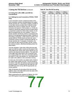
Table 69. Time-Slot Bit Decoding
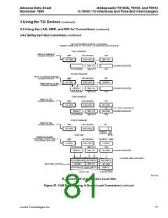
3 Using the TSI Devices (continued)
Address
Value
2 Mbits/s
Time Slot Time Slot Time Slot
4 Mbits/s
8 Mbits/s
3.4 Using the LAR, AMR, and IDR for
Connections
0x00
0x01
0x02
0x03
0x04
0x05
0x06
0x07
0x08
0x09
0x0A
0x0B
0x0C
0x0D
0x0E
0x0F
0x10
0x11
:
0
1
0
1
0
1
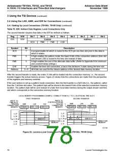
3.4.1 Setting Up Local Connections (T8100A, T8105
Only)
2
2
2
3
3
3
Local connections require a physical location in the
local connection memory corresponding to the output
stream and time slot. The location contains a pointer to
a local data memory location which holds the actual
data that has come in or will be sent out. The local
memories are based on 1024 locations, so 10 bits are
required to specify the physical memory location where
a connection is placed or where data is stored. To sim-
plify the programming, the user supplies 11 bits in a
stream and time-slot format, which is converted by the
devices to the appropriate physical location. Relative to
describing a connection, a data memory location corre-
sponds with the FROM stream and time slot, and a
connection memory location corresponds with the TO
stream and time slot. To program a connection, the
user loads the data memory location into the connec-
tion memory location, effectively identifying where the
data resides.
4
4
4
5
5
5
6
6
6
7
7
7
8
8
8
9
9
9
10
11
12
13
14
15
16
17
:
10
11
12
13
14
15
16
17
:
10
11
12
13
14
15
16
17
:
The user programs 7 bits of the LAR for the time-slot
value (or 8 bits for pattern mode) and the lowest 4 bits
of the AMR for the stream value; these will then be con-
verted to the physical memory address. The upper bits
of the AMR select which field in the connection mem-
ory is being written into. Since the connection informa-
tion itself is 15 bits, two transfers (i.e., two fields) must
be made to the address in the connection memory.
0x1E
0x1F
0x20
:
30
31
NA
:
30
31
32
:
30
31
32
:
0x3E
0x3F
0x40
:
NA
NA
NA
:
62
63
NA
:
62
63
64
:
In each case, the transfer is an indirect write of data to
the indirect data register, the IDR: The first transfer is
the lowest 7 bits (time-slot address) of the desired data
memory location. It is placed in the IDR after the LAR
and AMR have been set up with the appropriate con-
nection address.
0x7E
0x7F
NA
NA
NA
NA
126
127
Table 69 illustrates the decoding of the time-slot bits
(address value in the table refers to the hex value of the
7 bits comprising time slot).
When programming the registers for fallback, the CKS
and CKW registers should be programmed last.
Lucent Technologies Inc.
73

 AGERE [ AGERE SYSTEMS ]