Ambassador T8100A, T8102, and T8105
H.100/H.110 Interfaces and Time-Slot Interchangers
Advance Data Sheet
November 1999
2 Architecture and Functional Description (continued)
2.9 Testing and Diagnostics (continued)
2.9.2 Diagnostics (continued)
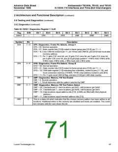
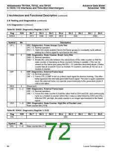
Table 64. DIAG2: Diagnostics Register 2, 0x31
Reg
R/W
Bit 7
Bit 6
Bit 5
Bit 4
Bit 3
Bit 2
Bit 1
Bit 0
DIAG2
—
DFC
DSB
DXF
RES
DSE
DSH
Symbol
Bit
Description
DFC
7
DFC: Diagnostics, Frame Groups Cycle Test
DFC = 0, Normal operation.
DFC = 1, Cycle test mode enabled; forces the frame groups to constantly cycle without
waiting for a frame signal to synchronize the start.
DSB
DXF
6
5
DSB: Diagnostics, State Counter, Break Carry Bits
DSB = 0, Normal operation.
DSB = 1, Breaks the carry bits between the subsections of the state counter so that the
state counter is operating as three counters running in parallel. (This can be
viewed on the frame pins using the DFn = 01 selection described above.) Status
counter bits [0:3] and [4:7] run as modulo-16 counters, and bits [8:10] run as a
modulo-8 counter.
DXF: Diagnostics, External Frame Input
DXF = 0, Normal operation.
DXF = 1, Forces /FR_COMP to act as a direct input signal for devices framing. This effec-
tively bypasses the internally generated frame signal. The user is again cautioned
since the external frame can operate asynchronously to the generated clocks if
care is not taken.
RES
DSE
4
(Reserved.)
3—2
DSE: Diagnostics, External Frame Input
DSE = 0, Normal operation.
DSE = 1, Forces the state counter to load the value held in DSH and DSL and continuously
cycle as a modulo-n counter where the n value is determined by (DSH and DSL).
With the DSE pin high, the state counter is no longer synchronized to the frame
signal.
DSH
1—0
DSH: Diagnostics, State Counter, High Bits of Parallel Load
State counter bits [10:8].
Table 65. DIAG3: Diagnostics Register 3, 0x32
Reg
R/W
Bit 7
Bit 6
Bit 5
Bit 4
Bit 3
Bit 2
Bit 1
Bit 0
DSL
—
DSL
Symbol
Bit
Description
DSL
7—0
State counter bits [7:0].
68
Lucent Technologies Inc.

 AGERE [ AGERE SYSTEMS ]