Ambassador T8100A, T8102, and T8105
H.100/H.110 Interfaces and Time-Slot Interchangers
Advance Data Sheet
November 1999
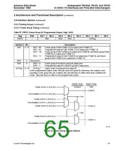
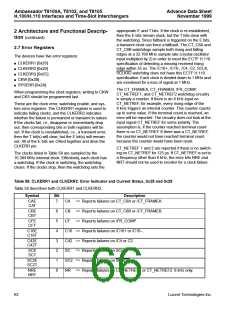
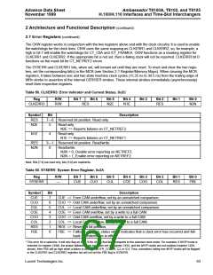
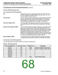
2 Architecture and Functional Description (continued)
2.8 The JTAG Test Access Port (continued)
2.8.3 Elements of JTAG Logic
The signal TRST, which is used for resetting the JTAG TAP controller, must be asserted to make the simulation
model (VHDL or Verilog* or encrypted Verilog) operate. Since the TAP controller does not always power up in nor-
mal mode, the TPA controller has to be reset. Resetting the TAP controller is done by asserting TRST (brought low)
and keeping it low throughout the test.
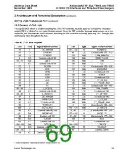
Table 62. JTAG Scan Register
Cell
Type
Signal Name/Function
Cell
Type
Signal Name/Function
66
67
I
O
CK_3MHZIN
SYSERR
121—132
O
FGA[11:0]
Controls cells 121—132
C16N_MINUSA
C16N_PLUSA
C4N
64
133
134
135
136
5
CC
Bdir
Bdir
Bdir
Bdir
CC
Bdir
CC
Bdir
CC
Bdir
Bdir
CC
Bdir
CC
Bdir
CC
Bdir
Bdir
CC
Bdir
CC
O
68
O
CLKERR
0
CC
Bdir
CC
I
Controls cells 67:68
D[0:7]
69—76
1
Controls cells 69:76
RESTN
C2
77
Controls cells 133—136
SCLKX2NA
78
O
RDY
137
7
79
I
WRN
Controls cell 137
SCLKA
80
I
RDN
138
6
81
I
CSN
Controls cell 138
CT_C8_BA
82
I
ALE
139
140
3
83
I
A0
CT_FRAME_BNA
Controls cells 139—140
FRN_COMPA
Controls cell 141
CT_NETREF
84
I
A1
85—88
44
O
L_SC[0:3]
141
4
CC
I
Controls cells 85:88
L_REF[0:7]
CK_4MHZIN
PRIREFOUT
Controls cell 98
TESTOUT1
REFCLK1O
Controls cells 99, 100
FROMDJAT
Controls cell 101
TODJAT
89—96
97
142
8
I
Controls cell 142
CT_C8_AA
98
O
143
144
2
45
CC
O
CT_FRAME_ANA
Controls cells 143—144
CT_D[0:31]
99
100
46
O
145—176
9—40
177—192
47—62
193
0
CC
Bdir
CC
Bdir
CC
Bdir
CC
O
Controls cells 145—176
LDO[0:15]
101
43
CC
O
Controls cells 177—192
XCS
102
42
Controls cell 102
GP[5:0]
CC
I
Controls cell 193
LDI[0:15]
103—108
41
194—209
210
65
Controls cells 103—108
FGB[11:0]
O
TCLKOUT
109—120
63
CC
Controls cell 65
CC
Controls cells 109—120
* Verilog is registered trademark of Cadence Design Systems, Inc.
Lucent Technologies Inc.
65

 AGERE [ AGERE SYSTEMS ]