Ambassador T8100A, T8102, and T8105
H.100/H.110 Interfaces and Time-Slot Interchangers
Advance Data Sheet
November 1999
2.9.2 Diagnostics
2 Architecture and Functional Descrip-
tion (continued)
The devices have onboard diagnostic modes for testing
the frame groups, SRAMs and CAMs, and some inter-
nal structures. These are intended for testing some of
the devices’ resources while in an application environ-
ment (rather than a manufacturing test environment).
2.9 Testing and Diagnostics
The devices have several testing operations:
■ JTAG
The diagnostics allow critical internal nodes to be out-
put through the frame groups, or to have the frame
groups operated in special cyclical manner, or to pro-
vide automatic filling of all memories (including CAMs)
with one of four selected patterns. The diagnostics are
activated and selected using three registers: DIAG1
[0x30], DIAG2 [0x31], or DIAG3 [0x32].
■ Forced output testing
■ Onboard diagnostics
During manufacturing, the devices are run through
standard functional and electrical testing.
2.9.1 Testing Operations
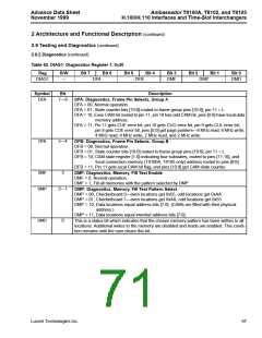
DIAG1 is used to select the frame group pins as either
monitors for internal nodes or normal operation (i.e., as
frame groups or programmed outputs). DIAG1 is also
used to control the memory fill diagnostic.
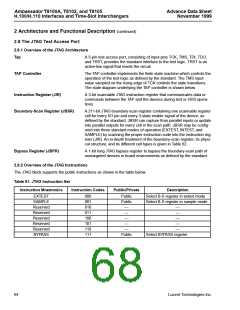
JTAG is used primarily to test the array portion of the
devices. It will not provide coverage for the CAMs, reg-
ister files, SRAMs, or PLLs. In JTAG, the manufacturer
provides a drop-in control block and scan-chain which
ties internal points to registers on the periphery of the
devices, which are, in turn, tied to the I/O pins. Serial
bit patterns are shifted into the devices through the TDI
pin, and the results can be observed at the I/O and at a
corresponding JTAG serial output, TDO. Since this
JTAG conforms to the JTAG standard, the TDI and TDO
can be linked to the JTAGs of other devices for sys-
temic testing. The TTS pin must be low for JTAG opera-
tions to work. The TTS pin has an internal pull-down
resistor that defaults the devices to JTAG operations.
DIAG2 and DIAG3 modify the normal operation of the
frame groups and the main state counter. Normally, the
frame groups begin their cascade sequence when the
state counter (i.e., the frame-synchronized master
counter of the devices) reaches a value equal to the
frame group’s starting address. DIAG2 and DIAG3
allow the state counter to be modified for one of two dif-
ferent tests.
When using the diagnostics in the pattern fill modes,
refer to Appendix C.
In forced output testing, the outputs are set to a particu-
lar state to measure their dc parameters. This can also
be used in applications for board-level diagnostics.
Forced output testing is selected by setting the TTS
(test type select) pin high. In this mode, the JTAG clock
pin, TCLK, will act as an input pin. All outputs will be
enabled, and each output provides either an inverting
or normal response to the input pin. Adjacent pins
alternate inverting and normal function (i.e., a checker-
board pattern).
66
Lucent Technologies Inc.

 AGERE [ AGERE SYSTEMS ]