Ambassador T8100A, T8102, and T8105
H.100/H.110 Interfaces and Time-Slot Interchangers
Advance Data Sheet
November 1999
appropriate E and T bits. If the clock is re-established,
then the E bits remain stuck, but the T bits clear with
the watchdog. Since fallback is triggered on the E bits,
a transient clock can force a fallback. The CT_C8A and
CT_C8B watchdogs sample both rising and falling
edges at a 32.768 MHz sample rate (crystal oscillator
input multiplied by 2) in order to meet the ECTF H.110
specification of detecting a missing received rising
edge within 35 ns. The /C16+, /C16-, /C4, C2, SCLK,
SCLKX2 watchdog does not have this ECTF H.110
specification. Each clock is divided down to 1 MHz and
are monitored for a loss of signal at 1 MHz.
2 Architecture and Functional Descrip-
tion (continued)
2.7 Error Registers
The devices have five error registers:
■ CLKERR1 [0x28]
■ CLKERR2 [0x29]
■ CLKERR3 [0x2C]
■ CKW [0x2B]
■ SYSERR [0x2A]
The CT_FRAMEA, CT_FRAMEB, /FR_COMP,
CT_NETREF1, and CT_NETREF2 watchdog circuitry
is simply a counter. If there is an 8 kHz input on
CT_NETREF, for example, every rising edge of the
8 kHz triggers an internal counter. This counter counts
up to some value. If the terminal count is reached, an
error will be reported. The circuitry does not look at the
input signal CT_NETREF for some polarity. The
assumption is, if the counter reached terminal count
there is no CT_NETREF. If there was a CT_NETREF,
the counter would not have reached terminal count
because the counter would have been reset.
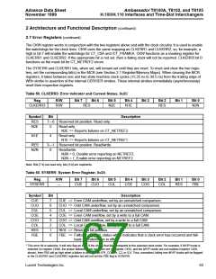
When programming the clock registers, writing to CKW
and CKS should be programmed last.
These are the clock error, watchdog enable, and sys-
tem error registers. The CLKERR1 register is used to
indicate failing clocks, and the CLKERR2 indicates
whether the failure is permanent or transient in nature.
If the clocks fail, i.e., disappear or momentarily drop
out, then corresponding bits in both registers will be
set. If the clock is reestablished, i.e., a transient error,
then the T bit(s) will clear, but the E bit(s) will remain
set. All of the E bits are ORed together and drive the
CLKERR pin.
CT_NETREF 1 and 2 are reported if there is no switch-
ing on CT_NETREF for 125 µs. If CT_NETREF is set to
a frequency other than 8 kHz, the error bits NRE and
NRT should not be used to monitor for a clock failure.
The clocks listed in Table 58 are sampled by the
16.384 MHz internal clock. Effectively, each clock has
a watchdog. If the clock is switching, the watchdog
clears. If the clocks stop, then the watchdog sets the
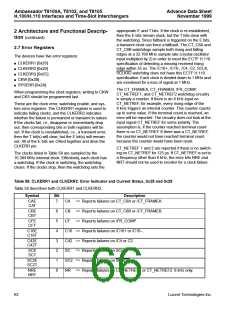
Table 58. CLKERR1 and CLKERR2: Error Indicator and Current Status, 0x28 and 0x29
Table 58 describes both CLKERR1 and CLKERR2.
Symbol
Bit
Description
CAE
CAT
7
CA => Reports failures on CT_C8A or /CT_FRAMEA.
CBE
CBT
6
5
4
3
2
1
0
CB => Reports failures on CT_C8B or /CT_FRAMEB.
CF => Reports failures on /FR_COMP.
CFE
CFT
C16E
C16T
C16 => Reports failures on /C16+ or /C16–.
C42 => Reports failures on /C4 or C2.
C42E
C42T
SCE
SCT
SC => Reports failures on SCLK.
SC2E
SC2T
SC2 => Reports failures on SCLKX2.
NRE
NRT
NR => Reports failures on CT_NETREF1 or CT_NETREF2. 8 kHz only.
62
Lucent Technologies Inc.

 AGERE [ AGERE SYSTEMS ]