Ambassador T8100A, T8102, and T8105
H.100/H.110 Interfaces and Time-Slot Interchangers
Advance Data Sheet
November 1999
posed to meet 32 ppm stability and 1 µs MTIE compli-
ance, and will in turn remain Stratum 4e on the out-
bound side. External trunks, T1 or E1, must be run
through framers (and a jitter attenuator, if not present in
the framer) to help ensure the input requirement. Given
this, the T810X is compliant in that it will not introduce
phase hits into the system which are uncontrolled, nei-
ther as high frequency (jitter) nor as low frequency
(wander).
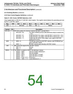
2 Architecture and Functional Descrip-
tion (continued)
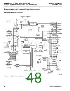
2.5 Clocking Section (continued)
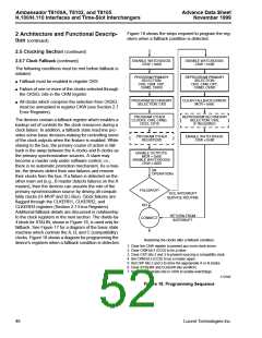
2.5.5 Bit Sliding (Frame Locking) (continued)
The devices generate frame signals based on the
incoming clock and frame references and device gen-
erated clock signals. When slaving, it is sometimes
necessary to align the edges of this generated frame
signal to the incoming frame reference.
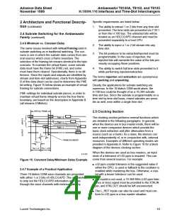
For a given clock, the T810X should respond in such a
way that the wander does not perturb the outbound
clocks greater than 61 ns per 2.048 MHz cycle, or more
than a total of 750 ns over any 1 ms measuring period.
These numbers are aided by the analog PLL. Any
phase hit is smoothed to 800 ps/65 MHz clock cycle
which is 25.6 ns/2.048 MHz clock cycle. Thus, the
61 ns/bit time is met. The 750 ns number is constrained
by the input requirement. Given that the inbound side
will be no greater than 750 ns over the 1 ms sampling
period, the T810X's outbound clocks will show a
maximum deviation in the 1 ms period on the order of
315 ns. In truth, framers, with accurate crystals, tend to
absorb much of the wander in slip buffers, so this num-
ber should be very small.
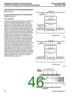
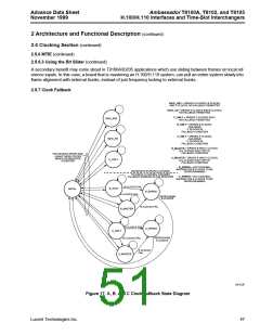
To accomplish this, the devices will compare the
referenced frames with the current state of its clock
state machine, and if the difference exceeds one
65.536 MHz clock cycle, the entire stream will have a
fraction of a bit time removed from each frame; this is
referred to as bit sliding. The process will repeat until
the measurements fall within one clock cycle. The
actual bit sliding will take place by reducing the gener-
ated frame by one 65.536 MHz clock cycle at the
beginning of the frame. This means that the frame
edges will phase-align at the rate of approximately
15.26 ns per frame. The maximum phase difference is
slightly less than one frame or 124.985 µs. Thus, it will
require approximately 8000 frames, or 1 second, to
phase-align the frame. This is mean time interval error
(MTIE) complaint.
While not a specific requirement of Stratum 4e, all
T810X products do provide holdover capability. The
T810X will respond, in a controlled fashion, to a change
of clock source. Again, the measurement method
for this uses the MTIE specification. The worst-case
response will be a 25.6 ns shift of clock edge per
0.048 MHz clock cycle less than the MTIE specifica-
tion.
The alternatives to bit sliding are snap alignment and
no alignment. Snap alignment refers to an instanta-
neous phase alignment, i.e., a reset at the frame
boundary. This mode is common to other devices. If no
alignment is chosen, the device’s generated frame is
frequency-locked to the incoming frame sync, but not
phase-aligned.
2.5.6.2 Relationship of the Bit Slider to MTIE
Strictly speaking, the bit slider is not related to MTIE in
that MTIE makes no provision for frame wander. The bit
slider itself however, will not introduce more than
15.26 ns/frame of additional shift, when enabled. The
slider does not affect the PLL or the clocks on a con-
stant basis, it simply walks the generated frame into
alignment with the received frame. Thus, the stability
of the clock edges remains constant in the long term,
but individual edges may deviate by an additional
amount, making the edge-to-edge absolute maximum
25.6 ns + 15.3 ns = 40.9 ns.
2.5.6 MTIE
MTIE is defined in AT&T technical reference TR62411.
MTIE is a characteristic of wander. Wander is defined
as clock phase deviations that are less than 10 Hz in
frequency. MTIE defines the amplitude of the wander.
The maximum amplitude, in the DS1/T1 world, is 1 µs
(about 1.5 bit times). This is measured by sampling the
delta of actual clock edges from the ideal positions over
2048 bit times (1.326 ms). The secondary requirement
is that no two edges may deviate by more than 81 ns
(1/8 bit time).
The critical item to relating MTIE with the bit slider is
that the bit slider won't make the T810X fail MTIE.
2.5.6.3 Using the Bit Slider
Apply this to the essentially E1-like timing in the
H.100/110/MVIP/SC-Bus worlds:
The bit slider is primarily intended for maintaining the
local side of an application. Specifically, some DSPs
have limited synchronizing ability and once they are
phase-aligned with the frame, a loss of frame sync can
be disruptive. The bit slider allows a change of source
to gracefully realign to a new frame without tripping up
the synchronization. There is limited benefit on the
H.100 side—snap mode is equivalent to slide in terms
of A/B clock fail-over, but the local side is much differ-
ent.
1.5 bit times is about 750 ns
2048 samples is 1 ms
1/8 bit time is about 61 ns
2.5.6.1 MTIE Compliance
T810X is MTIE compliant; however, the user must pay
attention to the system application. The T810X
requires Stratum 4e clocks, which are already sup-
46
Lucent Technologies Inc.

 AGERE [ AGERE SYSTEMS ]