Ambassador T8100A, T8102, and T8105
H.100/H.110 Interfaces and Time-Slot Interchangers
Advance Data Sheet
November 1999
2 Architecture and Functional Description (continued)
2.2 Local Bus Section (continued)
2.2.3 Data Rates and Time-Slot Allocation (continued)
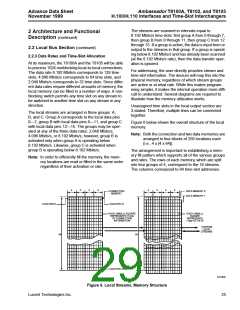
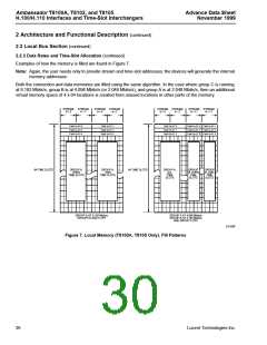
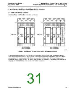
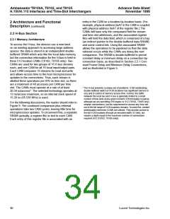
Examples of how the memory is filled are found in Figure 7.
Note: Again, the user needs only to provide stream and time-slot addresses; the devices will generate the internal
memory addresses.
Both the connection and data memories are filled using the same algorithm. In the case where group C is running
at 8.192 Mbits/s, group B is at 4.096 Mbits/s (or 2.048 Mbits/s), and group A is at 2.048 Mbits/s, then an additional
virtual memory space of 4 x 64 locations is created from unused locations in other parts of the memory.
STREAM STREAM
0—3 4—7
STREAM STREAM
0—3 4—7
STREAM STREAM
0—3 4—7
STREAM STREAM
8—11 8—11
TIME SLOT 0
TIME SLOT 1
TIME SLOT 0
TIME SLOT 0 TIME SLOT 1
TIME SLOT 2 TIME SLOT 3
TIME SLOT 4 TIME SLOT 5
TIME SLOT 2
TIME SLOT 4
TIME SLOT 3
TIME SLOT 5
TIME SLOT 1
TIME SLOT 2
64 TIME SLOTS
GROUP A,
EVEN
TIME SLOTS
GROUP A,
ODD
TIME SLOTS
64 TIME SLOTS
GROUP A,
ALL
GROUP
B, EVEN
TIME
GROUP
B, ODD
TIME
TIME
SLOTS
SLOTS
SLOTS
GROUP A AT 8.192 Mbits/s
GROUPS B AND C OFF
GROUP A AT 4.096 Mbits/s
GROUP B AT 8.192 Mbits/s
AND GROUP C OFF
5-6105F
Figure 7. Local Memory (T8100A, T8105 Only), Fill Patterns
26
Lucent Technologies Inc.

 AGERE [ AGERE SYSTEMS ]