Ambassador T8100A, T8102, and T8105
H.100/H.110 Interfaces and Time-Slot Interchangers
Advance Data Sheet
November 1999
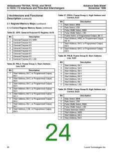
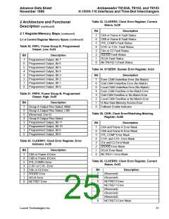
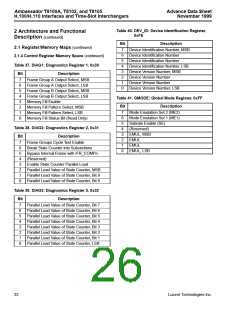
2 Architecture and Functional Description (continued)
2.2 Local Bus Section (continued)
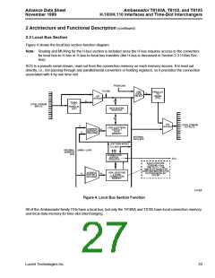
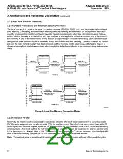
2.2.1 Constant Frame Delay and Minimum Delay Connections
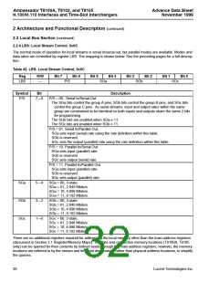
The local bus section contains the local connection memory (T8100A, T8105 only) and the double-buffered local
data memory. Collectively, the connection memory and data memory are referred to as local memory since it is
used for implementing local-to-local switching only. Operation is similar to other time-slot interchangers. Data is
written into the memory in a fixed order and then read out according to the indirect addresses held in the connec-
tion memory. If any of the connections on the devices are operating in constant frame delay (also called constant
delay) mode, then the output data is accessed from a second block of data memory. The input data will not be out-
put until the next frame boundary has been crossed and the memory blocks have swapped functions. Figure 5
shows an example of a set of connections which create the delay types referred to as minimum delay and constant
delay.
FRAME N DATA
FRAME N – 1 DATA
0
1
2
3
0
1
2
3
WRITE N
READ N
READ N – 1
CONSTANT DELAY
CONNECTION
MINIMUM DELAY
CONNECTION
1020
1021
1022
1023
1020
1021
1022
1023
DATA BLOCK 0
DATA BLOCK 1
FRAME N
FRAME N DATA
FRAME N + 1 DATA
0
1
2
3
0
1
2
3
READ N
WRITE N + 1
READ N + 1
MINIMUM DELAY
CONNECTION
CONSTANT DELAY
CONNECTION
1020
1021
1022
1023
1020
1021
1022
1023
DATA BLOCK 0
DATA BLOCK 1
FRAME N + 1
5-6103F
Figure 5. Local Bus Memory Connection Modes
2.2.2 Serial and Parallel
Nominally, the memory will be accessed by serial data streams which will require conversion of serial-to-parallel
(S/P) for write accesses and parallel-to-serial (P/S) for read accesses. Since the local memory can have up to 16
serial inputs and 16 serial outputs, there will be a maximum of 16 S/P converters and 16 P/S converters operating
simultaneously. If desired, eight of the S/P converters, local inputs 0—7, can be bypassed for a direct parallel write
to the data memory. Likewise, eight of the P/S converters, local outputs 0—7, can be bypassed for a direct parallel
read of the data memory. Unused S/P or P/S converters are nonfunctional in these modes.
Note: The normal serial-to-serial local streaming is not available simultaneously with any of the parallel modes.
24
Lucent Technologies Inc.

 AGERE [ AGERE SYSTEMS ]