AD5940
Data Sheet
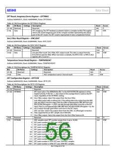
DFT Result, Imaginary Device Register—DFTIMAG
Address 0x0000207C, Reset: 0x00000000, Name: DFTIMAG
Table 45. Bit Descriptions for DFTIMAG Register
Bits
[31:18] Reserved
[17:0] Data
Bit Name Settings Description
Reset Access
Reserved.
0x0
0x0
R
DFT, imaginary. The DFT hardware accelerator returns a complex number. This register
returns the 18-bit imaginary part of the complex number representing the phase
part of the DFT result. The DFT result is represented in twos complement format.
R/W
Sinc2 Filter Result Register—SINC2DAT
Address 0x00002080, Reset: 0x00000000, Name: SINC2DAT
Table 46. Bit Descriptions for SINC2DAT Register
Bits
[31:16] Reserved
[15:0] Data
Bit Name Settings Description
Reset Access
Reserved.
0x0
0x0
R
Low-pass filter result. Sinc2 filter, ADC output result. This data is output from the
50 Hz/60 Hz rejection filter. When new data is available, the INTCFLAG1 or INTCFLAG2
registers, Bit 2 is set to 1.
R/W
Temperature Sensor Result Register—TEMPSENSDAT
Address 0x00002084, Reset: 0x00000000, Name: TEMPSENSDAT
Table 47. Bit Descriptions for TEMPSENSDAT Register
Bits
Bit Name
Reserved
Data
Settings
Description
Reset
0x0
Access
[31:16]
[15:0]
Reserved.
R
ADC temperature sensor channel result.
0x0
R/W
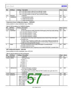
DFT Configuration Register—DFTCON
Address 0x000020D0, Reset: 0x00000090, Name: DFTCON
Table 48. Bit Descriptions for DFTCON Register
Bits
Bit Name
Settings Description
Reset Access
[31:22] Reserved
[21:20] DFTINSEL
Reserved.
0x0
0x0
R
DFT input select. The AVRGEN bit (Bit 7 in the ADCFILTERCON register) is of the
R/W
highest priority; if this bit = 1, the output of the average block is used as the DFT
input, regardless of the DFTINSEL setting.
00 Sinc2 filter output. Select the output from the Sinc2 filter.
Gain offset output with or without sinc3. This setting selects the output from the ADC
gain and offset correction stage. If the sinc3 filter is bypassed (the SINC3BYP bit in the
ADCFILTERCON register = 1), ADC raw data through gain/offset correction is the DFT
input. If sinc3 is not bypassed (the SINC3BYP bit in the ADCFILTERCON register = 0), the
01 sinc3 output through gain/offset correction is the DFT input.
ADC raw data. Selects the output direct from the ADC; no offset/gain correction.
10 Only supported for an ADC sample rate of 800 kHz.
11 Sinc2 filter output. Select the output from the Sinc2 filter Same as 00.
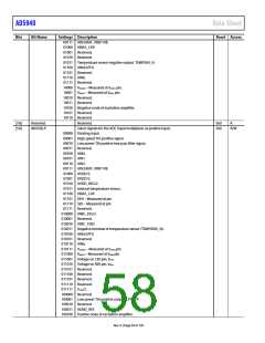
Reserved.
[19:8]
[7:4]
Reserved
DFTNUM
0x0
0x9
R
ADC samples used. DFT number ranges from 4 up to 16,384.
R/W
0
1
DFT point number is 4. DFT uses 4 ADC samples.
DFT point number is 8. DFT uses 8 ADC samples.
10 DFT point number is 16. DFT uses 16 ADC samples.
11 DFT point number is 32. DFT uses 32 ADC samples.
100 DFT point number is 64. DFT uses 64 ADC samples.
101 DFT point number is 128. DFT uses 128 ADC samples.
110 DFT point number is 256. DFT uses 256 ADC samples.
111 DFT point number is 512. DFT uses 512 ADC samples.
1000 DFT point number is 1024. DFT uses 1024 ADC samples.
1001 DFT point number is 2048. DFT uses 2048 ADC samples.
Rev. 0 | Page 56 of 130

 ADI [ ADI ]