ADSP-BF542/ADSP-BF544/ADSP-BF547/ADSP-BF548/ADSP-BF549
higher-priority event takes precedence over servicing of a lower-
priority event. The controller provides support for five different
types of events:
• Emulation. An emulation event causes the processor to
enter emulation mode, allowing command and control of
the processor via the JTAG interface.
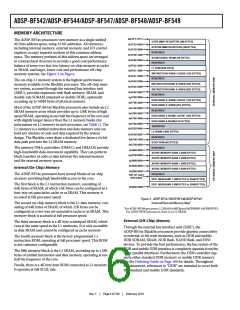
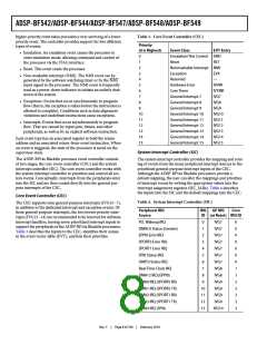
Table 3. Core Event Controller (CEC)
Priority
(0 is Highest)
0
Event Class
Emulation/Test Control EMU
Reset RST
Nonmaskable Interrupt NMI
EVT Entry
1
2
• Reset. This event resets the processor.
3
Exception
EVX
• Non-maskable interrupt (NMI). The NMI event can be
generated by the software watchdog timer or by the NMI
input signal to the processor. The NMI event is frequently
used as a power-down indicator to initiate an orderly shut-
down of the system.
• Exceptions. Events that occur synchronously to program
flow (that is, the exception is taken before the instruction is
allowed to complete). Conditions such as data alignment
violations and undefined instructions cause exceptions.
• Interrupts. Events that occur asynchronously to program
flow. They are caused by input pins, timers, and other
peripherals, as well as by an explicit software instruction.
Each event type has an associated register to hold the return
address and an associated return-from-event instruction. When
an event is triggered, the state of the processor is saved on the
supervisor stack.
4
Reserved
—
5
Hardware Error
IVHW
IVTMR
IVG7
6
Core Timer
7
General Interrupt 7
General Interrupt 8
General Interrupt 9
General Interrupt 10
General Interrupt 11
General Interrupt 12
General Interrupt 13
General Interrupt 14
General Interrupt 15
8
IVG8
9
IVG9
10
11
12
13
14
15
IVG10
IVG11
IVG12
IVG13
IVG14
IVG15
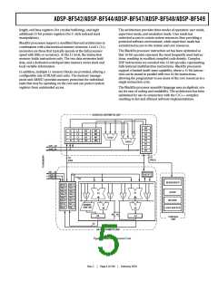
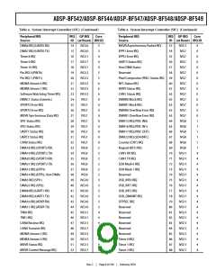
System Interrupt Controller (SIC)
The ADSP-BF54x Blackfin processor event controller consists
of two stages, the core event controller (CEC) and the system
interrupt controller (SIC). The core event controller works with
the system interrupt controller to prioritize and control all sys-
tem events. Conceptually, interrupts from the peripherals enter
into the SIC and are then routed directly into the general-pur-
pose interrupts of the CEC.
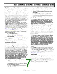
The system interrupt controller provides the mapping and rout-
ing of events from the many peripheral interrupt sources to the
prioritized general-purpose interrupt inputs of the CEC.
Although the ADSP-BF54x Blackfin processors provide a
default mapping, the user can alter the mappings and priorities
of interrupt events by writing the appropriate values into the
interrupt assignment registers (SIC_IARx). Table 4 describes
the inputs into the SIC and the default mappings into the CEC.
Core Event Controller (CEC)
Table 4. System Interrupt Controller (SIC)
The CEC supports nine general-purpose interrupts (IVG15–7),
in addition to the dedicated interrupt and exception events. Of
these general-purpose interrupts, the two lowest-priority inter-
rupts (IVG15–14) are recommended to be reserved for software
interrupt handlers, leaving seven prioritized interrupt inputs to
support the peripherals of the ADSP-BF54x Blackfin processors.
Table 3 describes the inputs to the CEC, identifies their names
in the event vector table (EVT), and lists their priorities.
Peripheral IRQ
Source
IRQ
GP IRQ
Core
ID (at Reset) IRQ ID
PLL Wakeup IRQ
0
1
IVG7
IVG7
IVG7
IVG7
IVG7
IVG7
IVG7
IVG8
IVG8
IVG9
IVG9
IVG9
IVG9
IVG10
0
0
0
0
0
0
0
1
1
2
2
2
2
3
DMAC0 Status (Generic)
EPPI0 Error IRQ
2
SPORT0 Error IRQ
3
SPORT1 Error IRQ
4
SPI0 Status IRQ
5
UART0 Status IRQ
6
Real-Time Clock IRQ
DMA12 IRQ (EPPI0)
DMA0 IRQ (SPORT0 RX)
DMA1 IRQ (SPORT0 TX)
DMA2 IRQ (SPORT1 RX)
DMA3 IRQ (SPORT1 TX)
DMA4 IRQ (SPI0)
7
8
9
10
11
12
13
Rev. C
|
Page 8 of 100
|
February 2010

 ADI [ ADI ]