ADSP-BF542/ADSP-BF544/ADSP-BF547/ADSP-BF548/ADSP-BF549
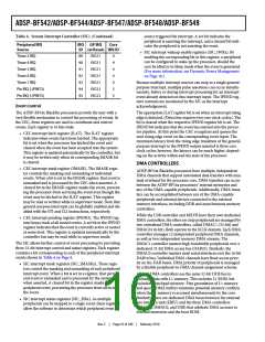
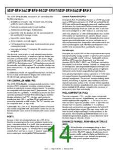
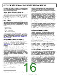
Connect RTC pins RTXI and RTXO with external components
as shown in Figure 4.
The timer units can be used in conjunction with the four
UARTs and the CAN controllers to measure the width of the
pulses in the data stream to provide a software auto-baud detect
function for the respective serial channels.
The timers can generate interrupts to the processor core, pro-
viding periodic events for synchronization to either the system
clock or to a count of external signals.
In addition to the general-purpose programmable timers,
another timer is also provided by the processor core. This extra
timer is clocked by the internal processor clock and is typically
used as a system tick clock for generation of periodic operating
system interrupts.
RTXI
RTXO
R1
X1
C1
C2
SUGGESTED COMPONENTS:
ECLIPTEK EC38J (THROUGH-HOLE PACKAGE)
EPSON MC405 12 pF LOAD (SURFACE-MOUNT PACKAGE)
C1 = 22 pF
C2 = 22 pF
R1 = 10 M:
UP/DOWN COUNTER AND THUMBWHEEL
INTERFACE
A 32-bit up/down counter is provided that can sense the 2-bit
quadrature or binary codes typically emitted by industrial drives
or manual thumb wheels. The counter can also operate in
general-purpose up/down count modes. Then count direction is
either controlled by a level-sensitive input pin or by two edge
detectors.
NOTE: C1 AND C2 ARE SPECIFIC TO CRYSTAL SPECIFIED FOR X1.
CONTACT CRYSTAL MANUFACTURER FOR DETAILS. C1 AND C2
SPECIFICATIONS ASSUME BOARD TRACE CAPACITANCE OF 3 pF.
Figure 4. External Components for RTC
WATCHDOG TIMER
A third input can provide flexible zero marker support and can
alternatively be used to input the push-button signal of thumb
wheels. All three pins have a programmable debouncing circuit.
An internal signal forwarded to the timer unit enables one timer
to measure the intervals between count events. Boundary regis-
ters enable auto-zero operation or simple system warning by
interrupts when programmable count values are exceeded.
The ADSP-BF54x processors include a 32-bit timer that can be
used to implement a software watchdog function. A software
watchdog can improve system reliability by forcing the proces-
sor to a known state through generation of a hardware reset,
non-maskable interrupt (NMI), or general-purpose interrupt if
the timer expires before being reset by software. The program-
mer initializes the count value of the timer, enables the
appropriate interrupt, and then enables the timer. Thereafter,
the software must reload the counter before it counts to zero
from the programmed value. This protects the system from
remaining in an unknown state where software, which would
normally reset the timer, has stopped running due to an external
noise condition or software error.
SERIAL PORTS (SPORTS)
The ADSP-BF54x Blackfin processors incorporate up to four
dual-channel synchronous serial ports (SPORT0, SPORT1,
SPORT2, and SPORT3) for serial and multiprocessor commu-
nications. The SPORTs support the following features:
• I2S capable operation.
• Bidirectional operation. Each SPORT has two sets of inde-
pendent transmit and receive pins, enabling up to eight
channels of I2S stereo audio.
• Buffered (8-deep) transmit and receive ports. Each port has
a data register for transferring data words to and from
other processor components and shift registers for shifting
data in and out of the data registers.
• Clocking. Each transmit and receive port can either use an
external serial clock or generate its own, in frequencies
ranging from (fSCLK/131,070) Hz to (fSCLK/2) Hz.
• Word length. Each SPORT supports serial data words from
3 to 32 bits in length, transferred most-significant-bit first
or least-significant-bit first.
• Framing. Each transmit and receive port can run with or
without frame sync signals for each data word. Frame sync
signals can be generated internally or externally, active high
or low, and with either of two pulse widths and early or late
frame sync.
If configured to generate a hardware reset, the watchdog timer
resets both the core and the ADSP-BF54x processors’ peripher-
als. After a reset, software can determine if the watchdog was the
source of the hardware reset by interrogating a status bit in the
watchdog timer control register.
The timer is clocked by the system clock (SCLK) at a maximum
frequency of fSCLK
.
TIMERS
There are up to two timer units in the ADSP-BF54x Blackfin
processors. One unit provides eight general-purpose program-
mable timers, and the other unit provides three. Each timer has
an external pin that can be configured either as a pulse width
modulator (PWM) or timer output, as an input to clock the
timer, or as a mechanism for measuring pulse widths and peri-
ods of external events. These timers can be synchronized to an
external clock input on the TMRx pins, an external clock
TMRCLK input pin, or to the internal SCLK.
Rev. C
|
Page 12 of 100
|
February 2010

 ADI [ ADI ]