AD9807/AD9805
OFFSET<M:0>
GAIN<N:0>
VREF
AD9807/AD9805
RED
VINR
VING
VINB
PGA
PGA
PGA
CDS
CDS
CDS
BANDGAP
REFERENCE
8-10
12-10/10-8
OEB
I/O
GREEN
DIGITAL
–
DIGITAL
X
12
12
12
12
12-BIT/10-BIT
MUX
DOUT<11:0>/MPU<7:0>
A/D
SUBTRACTOR
MULTIPLIER
3
INPUT OFFSET
REGISTER
8
CSB
RDB
WRB
A2
BLUE
R
R
EVEN
R
ODD
CONFIGURATION
REGISTER
MPU
PORT
G
B
G
B
G
B
ODD
EVEN
R
G
B
ODD
EVEN
CONFIGURATION
REGISTER
2
A1
A0
CDSCLK1 CDSCLK2 STRTLN ADCCLK
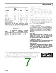
Figure 4. Block Diagram
7
6
5
4
3
2
1
0
REGISTER O VERVIEW
MP U P or t Map
T able II shows the MPU Port Map. T he MPU Port Map is
accessed through pins A0, A1 and A2 of the AD9807/AD9805,
and provides the decoding scheme for the various registers of
the AD9807/AD9805. When writing or reading from any of the
registers, the appropriate bits must be applied to A0–A2.
8X FULL SCALE
4X FULL SCALE
2X FULL SCALE
10-BIT GAIN, 10-BIT OFFSET
11-BIT GAIN, 9-BIT OFFSET
12-BIT GAIN, 8-BIT OFFSET
COLOR0
Table II. MP U P ort Map Form at
COLOR1
A2
A1
A0
Register
Figure 5. AD9807 Configuration Register Form at
0
0
0
0
1
1
1
1
0
0
1
1
0
0
1
1
0
1
0
1
0
1
0
1
Configuration Register
Configuration Register 2
PGA Gain Register
Odd Offset Register
Even Offset Register
Input Offset Register
RESERVED
Configur ation Register /AD 9805
T he Configuration Register controls three functions: a color
pointer, gain and offset pin configurations, and digital gain
scaling. Figure 6 shows the AD9805 Configuration Register.
Bits 0–2 control the digital scaling function. Setting a Bit
makes the corresponding condition true. Resetting Bits 0–2
disables and bypasses the digital multiplier. Bits 3–5 control
the gain and offset pin distribution. Resetting Bits 3–5 disables
and bypasses the digital subtracter and sets the gain word width
to 10. Setting any bit makes the corresponding condition true.
If Bit 3 is set, the 2 LSBs of the gain word become the 2 MSBs
of the offset word. If Bit 4 is set, the LSB of the gain word
becomes MSB of the offset word. Bits 6 and 7 direct register
data written to the MPU<7:0> bus to the appropriate red,
green or blue register.
Bayer Mode
Configur ation Register /AD 9807
T he Configuration Register controls three functions: a color
pointer, gain and offset pin configurations, and digital gain
scaling. Figure 5 shows the AD9807 Configuration Register.
Bits 0–2 control the digital scaling function. Setting a bit makes
the corresponding condition true. Resetting Bits 0–2 disables
and bypasses the digital multiplier. Bits 3–5 control the gain
and offset pin distribution. Resetting Bits 3–5 disables and
bypasses the digital subtracter and sets the gain word width to
12. Setting any bit makes the corresponding condition true. For
example, if Bit 3 is set, the 2 LSBs of the gain word become the
2 MSBs of the offset word. If Bit 4 is set, the LSB of the gain
word becomes MSB of the offset word. Bits 6 and 7 direct
register data written to the MPU<7:0> bus to the appropriate
red, green or blue register.
7
6
5
4
3
2
1
0
8X FULL SCALE
4X FULL SCALE
2X FULL SCALE
8-BIT GAIN, 10-BIT OFFSET
9-BIT GAIN, 9-BIT OFFSET
10-BIT GAIN, 8-BIT OFFSET
COLOR0
COLOR1
Figure 6. AD9805 Configuration Register Form at
REV. 0
–11–

 ADI [ ADI ]