AD9228
•
•
•
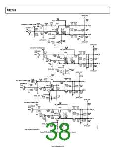
Remove R102, R115, R128, R141, T101, T102, T103, and
T104 in the default analog input path.
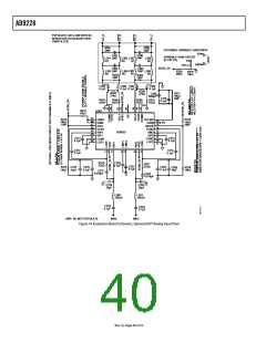
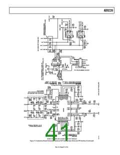
ALTERNATIVE ANALOG INPUT DRIVE
CONFIGURATION
The following is a brief description of the alternative analog
input drive configuration using the AD8332 dual VGA. If this
particular drive option is in use, some components may need to
be populated, in which case all the necessary components are
listed in Table 16. For more details on the AD8332 dual VGA,
including how it works and its optional pin settings, consult the
AD8332 data sheet.
Populate R101, R114, R127, and R140 with 0 Ω resistors in
the analog input path.
Populate R106, R107, R119, R120, R132, R133, R144, and
R145 with 10 kΩ resistors to provide an input common-
mode level to the analog input.
•
Populate R105, R113, R118, R124, R131, R137, R151, and
R160 with 0 Ω resistors in the analog input path.
To configure the analog input to drive the VGA instead of the
default transformer option, the following components need to
be removed and/or changed.
Currently, L301 to L308 and L401 to L408 are populated with 0 Ω
resistors to allow signal connection. This area allows the user to
design a filter if additional requirements are necessary.
Rev. 0 | Page 3ꢂ of 52

 ADI [ ADI ]