AD7858/AD7858L
CALIBRATION REGISTERS
The AD7858/AD7858L has 10 calibration registers in all, eight for the DAC, one for the offset, and one for gain. Data can be written
to or read from all 10 calibration registers. In self- and system calibration the part automatically modifies the calibration registers; only if the
user needs to modify the calibration registers should an attempt be made to read from and write to the calibration registers.
Addressing the Calibration Registers
The calibration selection bits in the control register CALSLT1 and CALSLT0 determine which of the calibration registers are ad-
dressed (see Table V). The addressing applies to both the read and write operations for the calibration registers. The user should not
attempt to read from and write to the calibration registers at the same time.
Table V. Calibration Register Addressing
CALSLT1 CALSLT0
Comment
0
0
1
1
0
1
0
1
This combination addresses the Gain (1), Offset (1) and DAC Registers (8). Ten registers in total.
This combination addresses the Gain (1) and Offset (1) Registers. Two registers in total.
This combination addresses the Offset Register. One register in total.
This combination addresses the Gain Register. One register in total.
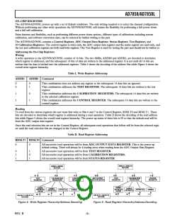
Writing to/Reading from the Calibration Registers
When reading from the calibration registers there will always be
two leading zeros for each of the registers. When operating in
Serial Interface Mode 1 the read operations to the calibration
registers cannot be aborted. The full number of read operations
must be completed (see section on Serial Interface Mode 1
Timing for more detail).
For writing to the calibration registers a write to the control
register is required to set the CALSLT0 and CALSLT1 bits.
For reading from the calibration registers a write to the control
register is required to set the CALSLT0 and CALSLT1 bits,
but also to set the RDSLT1 and RDSLT0 bits to 10 (this ad-
dresses the calibration registers for reading). The calibration
register pointer is reset on writing to the control register setting
the CALSLT1 and CALSLT0 bits, or upon completion of all
the calibration register write/read operations. When reset it
points to the first calibration register in the selected write/read
sequence. The calibration register pointer will point to the gain
calibration register upon reset in all but one case, this case being
where the offset calibration register is selected on its own
(CALSLT1 = 1, CALSLT0 = 0). Where more than one calibra-
tion register is being accessed the calibration register pointer will
be automatically incremented after each calibration register
write/read operation. The order in which the 10 calibration
registers are arranged is shown in Figure 7. The user may abort
at any time before all the calibration register write/read opera-
tions are completed, and the next control register write opera-
tion will reset the calibration register pointer. The flow chart in
Figure 8 shows the sequence for writing to the calibration regis-
ters and Figure 9 for reading.
START
WRITE TO CONTROL REGISTER SETTING STCAL = 0
AND CALSLT1, CALSLT0 = 00, 01, 10, 11
CAL REGISTER POINTER IS
AUTOMATICALLY RESET
WRITE TO CAL REGISTER
(ADDR1 = 1, ADDR0 = 0)
CAL REGISTER POINTER IS
AUTOMATICALLY INCREMENTED
LAST
REGISTER
NO
WRITE
OPERATION
OR
ABORT
?
CALIBRATION REGISTERS
CAL REGISTER
(1)
(2)
(3)
GAIN REGISTER
OFFSET REGISTER
ADDRESS POINTER
YES
FINISHED
DAC 1ST MSB REGISTER
CALIBRATION REGISTER
ADDRESS POINTER
.
.
.
.
.
.
.
.
.
.
.
.
.
.
.
.
.
.
.
.
.
Figure8. FlowchartforWritingtotheCalibrationRegisters
POSITION IS DETERMINED
BY THE NUMBER OF
CALIBRATION REGISTERS
ADDRESSED AND THE
NUMBER OF READ/WRITE
OPERATIONS
(10)
DAC 8TH MSB REGISTER
Figure 7. Calibration Register Arrangements
REV. B
–13–

 ADI [ ADI ]