AD7769
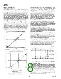
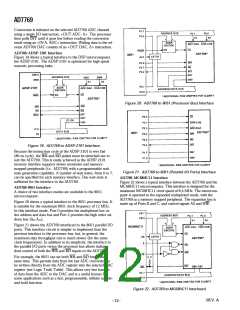
Figure 28. Generating a Software Program m able VSWING
(DAC)
For example, with a fixed input swing voltage of 2.5 V, the pro-
grammable span via DAC B is as follows:
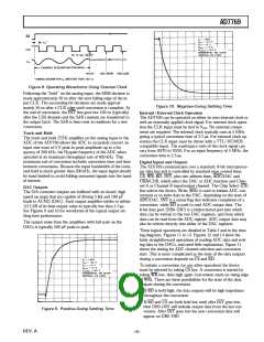
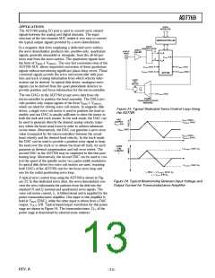
Figure 29. Typical Closed-Loop Microstepping Circuit
with the AD7769
DB = 0: VSWING (DAC) = 2.08
DB = 1/2: VSWING (DAC) = 2.5 V = VSWING
DB ≈ 1:
VSWING (DAC) = 3.125 V
T he AD7769 is specified for a VSWING (DAC) voltage range
from 2 V to 3 V, although in practice this range can be extended
while still maintaining monotonic operation.
Closed Loop Micr ostepping
Microstepping is a popular technique in low density disk drives
(both floppy and hard disk) that allows higher positional resolu-
tion of the disk drive head over that obtainable from a full-step
driven stepper motor. T ypically, a two-phase stepper motor has
its phase currents driven with a sine-cosine relationship. T hese
cosinusoidal signals are generated by two DACs driven with the
appropriate data. T he resolution of the DACs determines the
number of microsteps into which each full step can be divided.
For example, with a 1.8° full-step motor and a 4-bit DAC, a
microstep size of 0.11° (1.8°/2n) is obtainable.
T he microstepping technique improves the positioning resolu-
tion possible in any control application. However, the positional
accuracy can be significantly worse than that offered by the orig-
inal full-step accuracy specification due to load torque effects.
T o ensure that the increased resolution is usable, it is therefore
necessary to use a closed-loop system where the position of the
disk drive head (or motor) is monitored. T he closed-loop system
allows an error between the desired position and the actual posi-
tion to be monitored and corrected. T he correction is achieved
by adjusting the ratio of the phase currents in the motor wind-
ings until the required head position is reached.
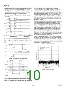
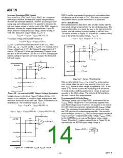
Figure 30. Typical Control Waveform s for the Microstep-
ping Circuit of Figure 29
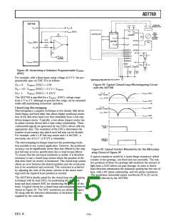
A typical transducer would be a moire-fringe transducer which
consists of two gratings, one fixed and one moveable. T he rela-
tive positions of these two gratings will modulate the amount of
light from a LED which can pass through. In order to derive
head direction information the stationary grating has two sets of
bars, with a 90° phase relationship, and two photo-transistors.
T he quadrature sinusoidal output waveforms (N & Q) can be
converted directly by the AD7769.
T he AD7769 is ideally suited for the closed-loop microstepping
technique with its dual DACs for positioning the disk drive
head and dual channel ADC for monitoring the position of the
head. A typical circuit for a closed-loop microstepping system is
shown in Figure 29. T he DAC waveforms are shown in Figure
30 along with the direction information of clockwise rotation
supplied by the controller.
REV. A
–15–

 ADI [ ADI ]