AD73360L
Cascade Operation
In Cascade Mode, both devices must know the number of devices
in the cascade to be able to output data at the correct time.
Control Register A contains a 3-bit field (DC0–2) that is pro-
grammed by the DSP during the programming phase. The default
condition is that the field contains 000b, which is equivalent to a
single device in cascade (see Table XVI). However, for cascade
operation this field must contain a binary value that is one less
than the number of devices in the cascade. With a cascade, each
device takes a turn to send an ADC result to the DSP. For
example, the data will be output as Device 2-Channel 1, Device
1-Channel 1, Device 2-Channel 2, Device 1-Channel 2 etc. When
the first device in the cascade has transmitted its channel data
there is an additional SCLK period during which the last device
asserts its SDOFS as it begins its transmission of the next chan-
nel. This will not cause a problem for most DSPs as they count
clock edges after a frame sync and hence the extra bit will be
ignored.
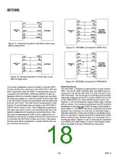
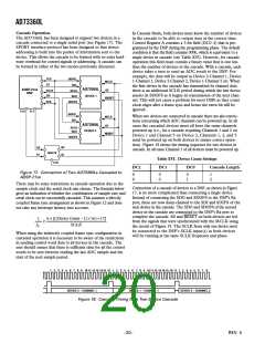
The AD73360L has been designed to support two devices in a
cascade connected to a single serial port (see Figure 17). The
SPORT interface protocol has been designed so that device
addressing is built into the packet of information sent to the
device. This allows the cascade to be formed with no extra hard-
ware overhead for control signals or addressing. A cascade can
be formed in either of the two modes previously discussed.
SDIFS
SDI
TFS
DT
MCLK
AD73360L
ADSP-21xx
DSP
SE
SCLK
DR
SCLK
SDO
DEVICE 1
RESET
RFS
SDOFS
FL0
FL1
SDIFS
SDI
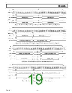
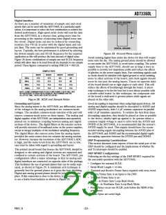
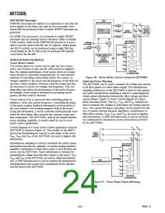
When two devices are connected in cascade there are also restric-
tions concerning which ADC channels can be powered up. In all
cases the cascaded devices must all have the same channels
powered up (i.e., for a cascade requiring Channels 1 and 2 on
Device 1 and Channel 5 on Device 2, Channels 1, 2, and 5
must be powered up on both devices to ensure correct opera-
tion). Figure 18 shows the timing sequence for two devices in
cascade. In all cases Channel 1 of all devices must be powered up.
MCLK
AD73360L
SE
SCLK
SDO
DEVICE 2
RESET
SDOFS
Q0
Q1
D0
D1
74HC74
Table XVI. Device Count Settings
CLK
DC2
DC1
DC0
Cascade Length
Figure 17. Connection of Two AD73360Ls Cascaded to
ADSP-21xx
0
0
0
0
0
1
1
2
There may be some restrictions in cascade operation due to the
sample clock and the serial clock rate chosen. The formula below
gives an indication of whether the combination of sample rate and
serial clock can be successfully cascaded. This assumes a directly
coupled frame sync arrangement as shown in Figure 12 and does
not take any interrupt latency into account.
Connection of a cascade of devices to a DSP, as shown in Figure
17, is no more complicated than connecting a single device.
Instead of connecting the SDO and SDOFS to the DSP’s Rx
port, these are now daisy-chained to the SDI and SDIFS of the
next device in the cascade. The SDO and SDOFS of the second
device in the cascade are connected to the DSP’s Rx port to
complete the cascade. SE and RESET on both devices are fed
from the signals that were synchronized with the MCLK using
the circuit of Figure 19. The SCLK from only one device need
be connected to the DSP’s SCLK input(s) as both devices
will be running at the same SCLK frequency and phase.
6 ×[((Device Count −1)×16)+17]
1
≥
fS
SCLK
When using the indirectly coupled frame sync configuration in
cascaded operation it is necessary to be aware of the restrictions
in sending control word data to all devices in the cascade. The
user should ensure that there is sufficient time for all the control
words to be sent between reading the last ADC sample and the
start of the next sample period.
1
2
3
4
5
6
7
8
9
10 11 12 13 14 15 16
1
2
3
4
5
6
7
8
9
10 11 12 13 14 15 16 17
1
2
3
4
5
6
7
8
DEVICE 2 – CHANNEL 1
DEVICE 1 – CHANNEL 1
DEVICE 2 – CHANNEL 2
Figure 18. Cascade Timing for a Two-Device Cascade
–20–
REV. 0

 ADI [ ADI ]