AD694
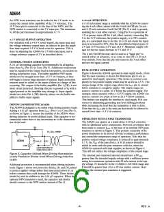
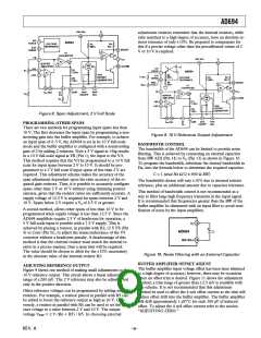
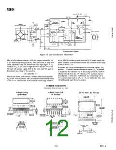
Figure 15. Low Cost Sensor Transmitter
The AD694 will now output a 4-20 mA output current for a 0
to 2 V differential swing across VA. The gain of the in amp front
end is adjusted so that the desired full-scale input signal at VIN
results in a VA of 2 V. For example a sensor that has a 100 mV
full scale will require a gain of 20 in the front end. The gain is
determined according to the equation:
by the AD708’s ability to pull down on RS. A single supply am-
plifier could be used instead to extend the common-mode range
down to about 1.5 V.
As shown, the circuit handles positive differential signals, (VIN
positive). To handle bipolar differential signals (VIN is positive
or negative), the reference pin of the in amp (point C) must be
offset positively from the 2 V reference. For example, discon-
nected point C from the 2 V reference and connecting it to a
3 V source would result in a VA of 1 V, (or half scale) for a zero
volt differential input from the sensor.
G = [2RS/Rg] + 1
The circuit shown, will convert a positive differential signal at
V
IN to a 4-20 mA current. The circuit has common-mode range
of 3 V to 8 V. The low end of the common-mode range is limited
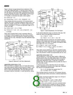
OUTLINE DIMENSIONS
Dimensions shown in inches and (mm).
16-Lead Cerdip
(Q) Package
16-Lead Plastic DIP
(N) Package
16-Pin SOIC (R) Package
–12–
REV. A

 ADI [ ADI ]