AD694
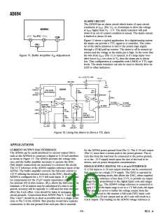
Figure 13. Digital to 4–20 mA Interface Using a Current Steering DAC
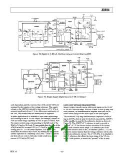
Figure 14. Single Supply Digital Input to 4–20 mA Output
code dependent, and the response time of the circuit will be de-
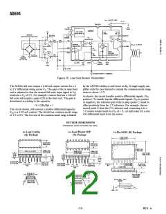
LOW COST SENSOR TRANSMITTER
termined by the reaction of the voltage reference. The supply
voltage to the AD7541A should be kept close to 15 V. If VS is
reduced significantly from 15 V the differential nonlinearity of
the DAC will increase and the linearity will be degraded.
Sensor bridges typically output differential signals in the 10 mV
to 100 mV full-scale range. With an AD694, a dual op amp, and
some resistors, an instrumentation amplifier front end can be
added which easily handles these types of low level signals.
In some applications it is desirable to have some under-range
and overrange in the 4–20 mA output. For example, assume an
over and under range capability of ±5% of span is needed, then
the output current range corresponding to the full scale of the
DAC is 3.2 mA to 20.8 mA. To accomplish this, the span of the
AD694 would be increased 10% to 17.6 mA by adding a nonin-
verting gain of 1.1 to the buffer amplifier. The 4 mA offset
would then be reduced by 0.8 mA, by utilizing the adjustment
scheme explained in “Adjusting 4 mA Zero.” Then a digital in-
put from all zero code to full scale would result in an output
current of 3.2 mA to 20.8 mA.
The traditional 3 op amp instrumentation amplifier is built us-
ing an AD708, dual op amp for the front end, and the AD694’s
buffer amplifier is used for the subtractor circuit, as shown in
Figure 15. The AD694’s 2 V reference is used to provide a
“ground” of 2 V that insures proper operation of the in amp
over a wide common mode range. The reference pin of the
subtractor circuit is tied to the 2 V reference (point C). A 2 kΩ
pull-down resistor insures that the voltage reference will be able
to sink any subtractor current. The 2 V FS (Pin 4) is attached to
the 2 V reference; this offsets the input range of the V/I con-
verter 2 volts positive, to match the “ground” of the in amp.
REV. A
–11–

 ADI [ ADI ]