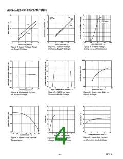
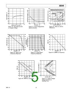
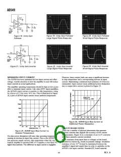
AD549
TEMPERATURE COMPENSATED pH PROBE
AMPLIFIER
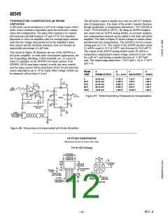
The pH probe output is ideally zero volts at a pH of 7 indepen-
dent of temperature. The slope of the probe’s transfer function,
though predictable, is temperature dependent (–54.2 mV/pH at
0 and –74.04 mV/pH at 100°C). By using an AD590 tempera-
ture sensor and an AD535 analog divider, an accurate tempera-
ture compensation network can be added to the basic pH probe
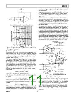
amplifier. The table in Figure 47 shows voltages at various points
and illustrates the compensation. The AD549 is set for a nonin-
verting gain of 13.51. The output of the AD590 circuitry (point
C) will be equal to 10 V at 100°C and decrease by 26.8 mV/°C.
The output of the AD535 analog divider (point D) will be a
temperature compensated output voltage centered at zero volts
for a pH of 7, and having a transfer function of –1.00 V/pH
unit. The output range spans from –7.00 V (pH = 14) to +7.00 V
(pH = 0).
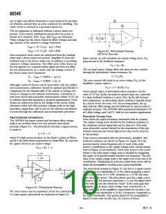
A pH probe can be modeled as a mV-level voltage source with a
series source resistance dependent upon the electrode’s compo-
sition and configuration. The glass bulb resistance of a typical
pH electrode pair falls between 106 and 109 Ω. It is therefore
important to select an amplifier with low enough input currents
such that the voltage drop produced by the amplifier’s input
bias current and the electrode resistance does not become an
appreciable percentage of a pH unit.
The circuit in Figure 46 illustrates the use of the AD549 as a
pH probe amplifier. As with other electrometer applications, the
use of guarding, shielding, Teflon standoffs, etc., is a must in
order to capitalize on the AD549’s low input current. If an
AD549L (60 fA max input current) is used, the error contrib-
uted by input current will be held below 60 µV for pH electrode
source impedances up to 109 Ω. Input offset voltage (which can
be trimmed) will be below 0.5 mV.
PROBE
A
B
C
D
TEMP
(PROBE OUTPUT)
(10 B/C)
0
54.20 mV
59.16 mV
61.54 mV
66.10 mV
0.732 V
0.799 V
0.831 V
0.893 V
7.32 V
7.99 V
8.31 V
8.93 V
1.00 V
1.00 V
1.00 V
1.00 V
25؇C
37؇C
60؇C
100؇C
74.04 mV
1.000 V
10.00 V
1.00 V
Figure 47. Table Illustrating Temperature Compensation
Figure 46. Temperature Compensated pH Probe Amplifier
OUTLINE DIMENSIONS
Dimensions shown in inches and (mm).
TO-99 (H) Package
0.370 (9.40)
0.335 (8.50)
0.2
(5.1)
TYP
0.335 (8.50)
0.305 (7.75)
0.040
(1.0)
MAX
3
45° EQUALLY
SPACED
0.185 (4.70)
0.165 (4.19)
2
8
4
6
1
5
REFFERENCE
PLANE
SEATING
PLANE
7
INSULATION
0.05 (1.27) MAX
0.500
(12.70)
MIN
0.034 (0.86)
0.028 (0.41)
0.045 (1.1)
8 LEADS
0.019 (0.48)
0.016 (0.41)
0.020 (0.51)
DIA
BOTTOM VIEW
–12–
REV. A

 ADI [ ADI ]