AD1819B
Slot 5–Slot 8: Multicodec Communication
• Slot 5 Slave 1 PCM Playback Left Channel
• Slot 6 Slave 1 PCM Playback Right Channel
• Slot 7 Slave 2 PCM Playback Left Channel
• Slot 8 Slave 2 PCM Playback Right Channel
Slot 6–Slot 12: Reserved
Audio output frame Slot 6 to Slot 12 are reserved for future use and should always be stuffed with 0s by the digital controller.
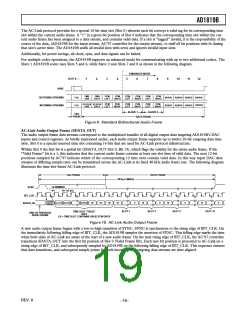
AC-Link Audio Input Frame (SDATA_IN)
The audio input frame data streams correspond to the multiplexed bundles of all digital input data targeting the AC’97 controller. As
is the case for audio output frame, each AC-Link audio input frame consists of twelve 20-bit time slots. Slot 0 is a special reserved
time slot containing 16 bits used for AC-Link protocol infrastructure.
Within Slot 0 the first bit is a global bit (SDATA_IN Slot 0, Bit 15) which flags whether or not AD1819B is in the “Codec Ready”
state. If the “Codec Ready” bit is a 0, this indicates that AD1819B is not ready for normal operation. This condition is normal fol-
lowing the deassertion of power-on reset, for example, while AD1819B’s voltage references settle. When the AC-Link “Codec Ready”
indicator bit is a 1, it indicates that the AC-Link and AD1819B control and status registers are in a fully operational state and all
subsections are ready.
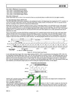
Prior to any attempts at putting AD1819B into operation the AC’97 controller should poll the first bit in the audio input frame
(SDATA_IN Slot 0, Bit 15) for an indication that the AD1819B has asserted “Codec Ready.” Once the AD1819B is sampled, “Codec
Ready” is asserted the next 12-bit positions sampled by the AC’97 controller indicate which of the corresponding 12 time slots are
assigned to input data streams and that they contain valid data. The following diagram illustrates the time-slot-based AC-Link protocol.
TAG PHASE
DATA PHASE
20.8s (48kHz)
SYNC
BIT_CLK
12.288MHz
81.4ns
CODEC
READY
“0”
“0”
“0”
19
SLOT(1) SLOT(2)
SLOT(12)
SDATA_IN
0
19
0
19
0
19
0
SLOT 1
SLOT 2
SLOT 3
SLOT 12
TIME SLOT “VALID”
BITS
(1) = TIME SLOT CONTAINS VALID PCM DATA
END OF PREVIOUS
AUDIO FRAME
Figure 12. AC-Link Audio Input Frame
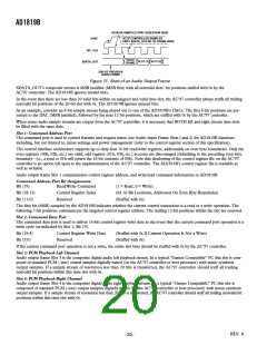
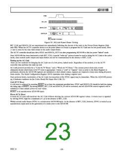
A new audio input frame begins with a low-to-high transition of SYNC. SYNC is synchronous to the rising edge of BIT_CLK. On
the immediately following falling edge of BIT_CLK, the AD1819B samples the assertion of SYNC. This falling edge marks the time
when both sides of AC-Link are aware of the start of a new audio frame. On the next rising of BIT_CLK, the AD1819B transitions
SDATA_IN into the first bit position of Slot 0 (“Codec Ready” bit). Each new bit position is presented to AC-Link on a rising edge of
BIT_CLK, and subsequently sampled by the AC’97 controller on the following falling edge of BIT_CLK. This sequence ensures that
data transitions, and subsequent sample points for both incoming and outgoing data streams, are time aligned.
AD1819A SAMPLES SYNC ASSERTION HERE
AC’97 CONTROLLER SAMPLES
SYNC
FIRST SDATA_IN BIT OF FRAME HERE
BIT_CLK
CODEC
READY
SDATA_IN
SLOT (1) SLOT (2)
END OF PREVIOUS
AUDIO FRAME
Figure 13. Start of an Audio Input Frame
SDATA_IN’s composite stream is MSB justified (MSB first) with all nonvalid bit positions (for assigned and/or unassigned time
slots) stuffed with 0s by AD1819B.
Slot 0: Tag Phase SDATA_IN
The AD1819B is capable of sampling data from 7 kHz to 48 kHz with a resolution of 1 kHz. To enable a sample rate other than the
default 48 kHz, set the DRQEN bit (Register 74h Bit 11). This allows DAC request bits (these are low active) to be output on the
SDATA_IN stream. The digital controller should monitor the ADC valid bits to determine when the codec has valid data ready to
send.
REV. 0
–21–

 ADI [ ADI ]