AD1819B
Sample Rate 0 (Index 78h)
Reg
Num
Name
D15
D14
D13
D12
D11
D10
D9
D8
D7
D6
D5
D4
D3
D2
D1
D0
Default
78h
Sample Rate 0
SR015 SR014 SR013 SR012 SR011 SR010 SR09
SR08
SR07
SR06
SR05
SR04
SR03
SR02
SR01
SR00 BB80h
SR0 [15:0]
Writing to this register allows the user to program the sampling frequency from 7 kHz (1B58h) to 48 kHz (BB80h)
in 1 Hz increments. Programming a value greater than 48 kHz or less than 7 kHz may cause unpredictable results.
Sample Rate 1 (Index 7Ah)
Reg
Num
Name
D15
D14
D13
D12
D11
D10
D9
D8
D7
D6
D5
D4
D3
D2
D1
D0
Default
7Ah
Sample Rate 1
SR115 SR114 SR113 SR112 SR111 SR110 SR19
SR18
SR17
SR16
SR15
SR14
SR13
SR12
SR11
SR10 BB80h
SR1 [15:0]
Writing to this register allows the user to program the sampling frequency from 7 kHz (1B58h) to 48 kHz (BB80h)
in 1 Hz increments. The sample rate may be multiplied by 8/7 or 10/7 by setting Bits D6 and D5 in Register 76h.
Vendor ID (Index 7Ch–7Eh)
Reg
Num
Name
D15
D14
D13
D12
D11
D10
D9
D8
D7
D6
D5
D4
D3
D2
D1
D0
Default
7Ch
Vendor ID1
F7
F6
F5
F4
F3
F2
F1
F0
S7
S6
S5
S4
S3
S2
S1
S0
4144h
S [7:0]
F [7:0]
This register is ASCII encoded to “A.”
This register is ASCII encoded to “D.”
Reg
Num
Name
D15
D14
D13
D12
D11
D10
D9
D8
D7
D6
D5
D4
D3
D2
D1
D0
Default
7Eh
Vendor ID2
T7
T6
T5
T4
T3
T2
T1
T0
REV7 REV6 REV5 REV4 REV3 REV2 REV1 REV0 5303h
T [7:0]
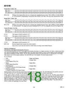
This register is ASCII encoded to “S.”
Revision Register field contains the revision number.
These bits are read-only and should be verified before accessing vendor-defined features.
REV [7:0]
DIGITAL INTERFACE
AD1819B AC-Link Digital Serial Interface Protocol
The AD1819B incorporates an AC'97 5-pin digital serial interface that links it to a digital controller. AC-Link is a bidirectional, fixed
rate, serial PCM digital stream. It handles multiple input, and output audio streams, as well as control register accesses employing a
time division multiplexed (TDM) scheme. The AC-Link architecture divides each audio frame into 12 outgoing and 12 incoming
data streams, up to 20-bit sample resolution. The AD1819B uses 16-bit samples. The data streams include:
AC ’97 Protocol
•
•
TAG
1 Input and Output
2 Output Slots
Control
Control Register Write Port
•
•
•
Status
Control Register Read Port
2 Input Slots
2 Output Slots
2 Input Slots
PCM Playback
2-Channel Composite PCM Output Stream
PCM Record Data
2-Channel Composite PCM Input Stream
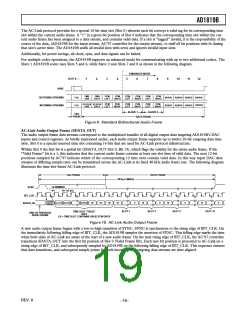
Synchronization of all AC-Link data transactions is signaled by the AC’97 controller. The AD1819B drives the serial bit clock onto
AC-Link, which the AC’97 controller then qualifies with a synchronization signal to construct audio frames.
SYNC, which is fixed at 48 kHz, is derived by dividing down the serial bit clock (BIT_CLK) by 256. The BIT_CLK is fixed at
12.288 MHz. AC-Link serial data is updated on each rising edge of BIT_CLK. The receiver of AC-Link data, the AD1819B for outgo-
ing data and the AC’97 controller for incoming data, samples each serial bit on the falling edge of BIT_CLK. SYNC must remain
high for a minimum of 1 BIT_CLK up to a maximum duration of 16 BIT_CLKs at the beginning of each audio frame. The first 16
bits of the audio frame is defined as the “Tag Phase.” The remainder of the audio frame is the “Data Phase.” The AD1819B uses
SYNC to define the beginning of the audio frame.
REV. 0
–18–

 ADI [ ADI ]