AD1819B
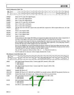
Serial Configuration (Index 74h)
Reg
Num
Name
D15
D14
D13
D12
D11
D10
D9
D8
D7
D6
D5
D4
D3
D2
D1
D0
Default
SLOT REGM REGM REGM DRQE DLRQ DLRQ DLRQ
16
DRRQ DRRQ DRRQ
74h
Serial Configuration
X
X
X
X
X
7000h
2
1
0
N
2
1
0
2
1
0
DRRQ0
DRRQ1
DRRQ2
DLRQ0
DLRQ1
DLRQ2
DRQEN
Master AC’97 Codec DAC Right Request.
Slave 1 Codec DAC Right Request.
Slave 2 Codec DAC Right Request.
Master AC’97 Codec DAC Left Request.
Slave 1 Codec DAC Left Request.
Slave 2 Codec DAC Left Request.
Fills idle status slots with DAC request reads, and stuffs DAC requests into LSB of output address slot. (AC-Link
Slot 1.)
REGM0
REGM1
REGM2
SLOT16
Master Codec Register Mask.
Slave 1 Codec Register Mask.
Slave 2 Codec Register Mask.
Enable 16-Bit Slots.
If your system uses only a single AD1819B, you can ignore the register mask and the slave 1/slave 2 request bits. If
you write to this register, write ones to all of the register mask bits. The request bits are read-only.
The codec asserts each request bit when the corresponding DAC channel can accept data in the next frame. These
bits are snapshots of the codec state taken when the current frame began (effectively, on the rising edge of SYNC),
but they also take notice of DAC samples sent in the current frame.
If you set the DRQEN bit, the AD1819B will fill all otherwise unused AC-Link status address and data slots with
the contents of register 74h. That makes it somewhat simpler to access the information, because you don’t need to
continually issue AC-Link read commands to get the register contents.
Also, the DAC requests are reflected in Slot 1, Bits (11 . . . 6). These bits are active Lo.
SLOT16 makes all AC-Link slots 16 bits in length, formatted into 16 slots.
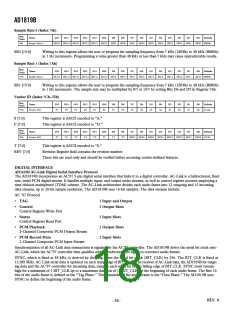
Miscellaneous Control Bits (Index 76h)
Reg
Num
Name
D15
D14
D13
D12
D11
D10
D9
D8
D7
D6
D5
D4
D3
D2
D1
D0
Default
MOD SRX10 SRX8
EN D7 D7
76h
Misc Control Bits
DACZ
X
X
X
X
DLSR
X
ALSR
X
X
DRSR
X
ARSR 0000h
ARSR
DRSR
ADC Right Sample Generator Select. Connects right ADC channel to SR0 or SR1.
0 = SR0 Selected.
1 = SR1 Selected.
DAC Right Sample Generator Select. Connects right DAC channel to SR0 or SR1.
0 = SR0 Selected.
1 = SR1 Selected.
SRX8D7
SRX10D7
MODEN
ALSR
Multiply SR1 Rate by 8/7.
Multiply SR1 Rate by 10/7. SRX10D7 and SRX8D7 are mutually exclusive; SRX10D7 has priority if both are set.
Modem Filter Enable (left channel only). Change only when DACs are powered down.
ADC Left Sample Generator Select. Connects left ADC channel to SR0 or SR1.
0 = SR0 Selected.
1 = SR1 Selected.
DLSR
DACZ
DAC Left Sample Generator Select. Connects left DAC channel to SR0 or SR1.
0 = SR0 Selected.
1 = SR1 Selected.
Zero-Fill (vs. repeat sample) if DAC is starved.
REV. 0
–17–

 ADI [ ADI ]