AD1819B
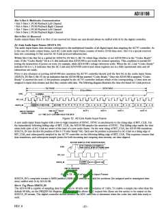
SYNC
BIT_CLK
SDATA_OUT
SDATA_IN
SLOT 12
PREVIOUS
FRAME
DATA
PR4
WRITE TO
0x26
TAG
TAG
SLOT 12
PREVIOUS
FRAME
NOTE:
BIT_CLK NOT TO SCALE
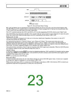
Figure 14. AC-Link Power-Down Timing
BIT_CLK and SDATA_IN are transitioned low immediately following the decode of the write to the Power-Down Register (26h)
with PR4. When the AC’97 controller driver is at the point where it is ready to program the AC-Link into its low power mode, Slots
(1 and 2) must be the only valid stream in the audio output frame.
The AC’97 controller should also drive SYNC and SDATA_OUT low after programming AD1819B to this low power “halted” mode.
Once AD1819B has been instructed to halt BIT_CLK, a special “wake-up” protocol must be used to bring the AC-Link to the active
mode, since normal audio output and input frames can not be communicated in the absence of BIT_CLK.
Waking up the AC-Link
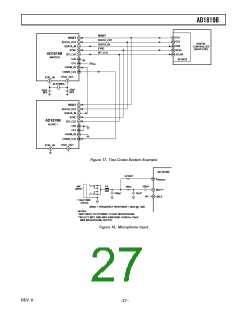
There are two methods for bringing the AC-Link out of a low power, halted mode. Regardless of the method, it is the AC’97
controller that performs the wake-up task.
AC-Link protocol provides for a “Cold AC’97 Reset,” and a “Warm AC’97 Reset.” The current power-down state would
ultimately dictate which form of AC’97 reset is appropriate. Unless a “cold” or “register” reset (a write to the Reset Register) is
performed, wherein the AD1819B registers are initialized to their default values, registers are required to keep state during all power-
down modes. The Serial Configuration Register (0x74) maintains state during a register reset.
Once powered down, reactivation of the AC-Link via reassertion of the SYNC signal may be immediate. When the AD1819B powers
up, it indicates readiness via the Codec Ready Bit (Input Slot 0, Bit 15).
Cold AC’97 Reset
A cold reset is achieved by asserting RESET for at least the minimum specified time. SYNC and SDATA_IN should be held low during
the rising edge of RESET. By driving RESET, BIT_CLK and SDATA_IN will be activated, and all AD1819B control registers will be
initialized to their default power-on reset values.
RESET is an asynchronous AD1819B input.
Warm AC’97 Reset
A warm AC’97 reset will reactivate the AC-Link without altering the current AD1819B register values. A warm reset is signaled
by driving SYNC high for a minimum of 1 µs in the absence of BIT_CLK.
Within normal audio frames SYNC is a synchronous AD1819B input. In the absence of BIT_CLK, however, SYNC is treated as an
asynchronous input used in the generation of a warm reset to the AD1819B.
REV. 0
–23–

 ADI [ ADI ]