AD1819B
TAG Phase Bit Assignments:
Bit (15)
Bit (14)
Bit (13)
Bit (12)
Bit (11)
Bit (10)
Bit (9)
Bit (8)
Bit (7)
Bit (6:0)
Codec Ready
Slot 1 Valid
Slot 2 Valid
Slot 3 Valid/ADC Left Data Is Valid on Slot 3
Slot 4 Valid/ADC Right Data Is Valid on Slot 4
Slot 5 Valid/ADC Left Data Slave 1 Valid on Slot 5
Slot 6 Valid/ADC Right Data Slave 1 Valid on Slot 6
Slot 7 Valid/ADC Left Data Slave 2 Valid on Slot 7
Slot 8 Valid/ADC Right Data Slave 2 Valid on Slot 8
Not Used
Slot 1: Status Address Port
The status port is used to monitor status for AD1819B functions including, but not limited to, mixer settings and power
management.
Audio input frame Slot 1’s stream echoes the control register index, for historical reference, for the data to be returned in Slot 2
(assuming that Slots 1 and 2 had been tagged “valid” by the AD1819B during Slot 0).
Status Address Port Bit Assignments:
Bit (19)
Bit (18:12)
Bit (11)
Bit (10)
Bit (9)
Bit (8)
Bit (7)
Bit (6)
Bit (5:0)
RESERVED
(Stuffed with 0)
(Echo of Register Index for Which Data Is Being Returned)
(0 = Request, 1 = No Request)
Control Register Index
DAC Request Slot 3
DAC Request Slot 4
DAC Request Slot 5
DAC Request Slot 6
DAC Request Slot 7
DAC Request Slot 8
RESERVED
(0 = Request, 1 = No Request)
(0 = Request, 1 = No Request); Slave 1
(0 = Request, 1 = No Request); Slave 1
(0 = Request, 1 = No Request); Slave 2
(0 = Request, 1 = No Request); Slave 2
(Stuffed with 0s)
The first bit (MSB) generated by the AD1819B is always stuffed with a 0. The following 7-bit positions communicate the associated
control register address, and the trailing 12-bit positions are stuffed with 0s by the AD1819B.
Slot 2: Status Data Port
The status data port delivers 16-bit control register read data.
Bit (19:4)
Bit (3:0)
Control Register Read Data
RESERVED
(Stuffed with 0s If Tagged “Invalid” by AD1819B)
(Stuffed with 0s)
If Slot 2 is tagged “invalid” by the AD1819B, the entire slot will be stuffed with 0s by the AD1819B.
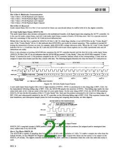
Slot 3: PCM Record Left Channel
Audio input frame Slot 3 is the left channel output of the AD1819B’s input MUX, post-ADC.
AD1819B transmits its ADC output data (MSB first), and stuffs the trailing nonvalid bit positions with 0s to fill out its 20-bit time slot.
Slot 4: PCM Record Right Channel
Audio input frame Slot 4 is the right channel output of the AD1819B’s input MUX, post-ADC.
AD1819B transmits its ADC output data (MSB first), and stuffs the trailing nonvalid bit positions with 0s to fill out its 20-bit time slot.
Slot 5–Slot 8: Multicodec Communication
• Slot 5 Slave 1 PCM Record Left Channel
• Slot 6 Slave 1 PCM Record Right Channel
• Slot 7 Slave 2 PCM Record Left Channel
• Slot 8 Slave 2 PCM Record Right Channel
Slot 9–Slot 12: Reserved
Audio input frame Slots 9–12 are reserved for future use and are always stuffed with 0s by the AD1819B.
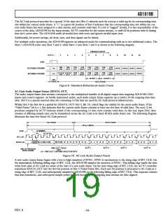
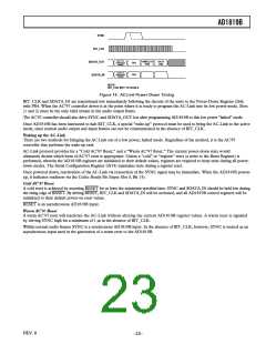
AC-Link Low Power Mode
The AC-Link signals can be placed in a low power mode. When the AD1819B’s Power-Down Register (26h) is programmed to the
appropriate value, both BIT_CLK and SDATA_IN will be brought to a logic low voltage level.
REV. 0
–22–

 ADI [ ADI ]