AD1819B
MIX
Mono Output Select.
0 = Mix.
1 = Mic.
3D
Phat Stereo Enhancement.
0 = Phat Stereo is off.
1 = Phat Stereo is on.
POP
PCM Output Path. The POP bit controls the optional PCM out 3D bypass path (the pre- and post-
3D PCM outpaths are mutually exclusive).
0 = Pre-3D.
1 = Post-3D.
The register should be read before writing to generate a mask for only the bit(s) that need to be changed. The
default value is 0000h.
3D Control (Index 22h)
Reg
Name
Num
D15
D14
D13
D12
D11
D10
D9
D8
D7
D6
D5
D4
D3
D2
D1
D0
Default
22h*
3D Control
X
X
X
X
X
X
X
X
X
X
X
X
DP3
DP2
DP1
DP0
0000h
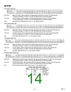
DP [2:0]
Depth Control. Sets 3D “Depth” Phat Stereo enhancement according to table below.
DP3 . . . DP0
Depth
0
1
0%
6.67%
14
15
93.33%
100%
Power-Down Control/Status (Index 26h)
Reg
Num
Name
D15
D14
D13
D12
D11
D10
D9
D8
D7
D6
D5
D4
D3
D2
ANL
D1
D0
Default
26h
Power-Down Cntrl/Stat
X
X
PR5
PR4
PR3
PR2
PR1
PR0
X
X
X
X
REF
DAC
ADC 0000h
Ready Bits: The ready bits are read only, writing to REF, ANL, DAC, ADC will have no effect. These bits indi-
cate the status for the AD1819B subsections. If the bit is a one then that subsection is “ready.” Ready is defined as
the subsection able to perform in its nominal state.
ADC
ADC section ready to transmit data.
DAC
DAC section ready to accept data.
ANL
Analog gainuators, attenuators, and mixers ready.
Voltage References, VREF and VREFOUT up to nominal level.
REF
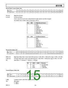
PR [5:0]
Power-Down Bits. Bits 0 and 1 are to be used individually rather than in combination with each other. The last bit
PR3 can be used in combination with PR2 or by itself.
Power-Down State
Set Bits
ADCs and Input Mux Power-Down
DACs Power-Down
PR0
PR1
Analog Mixer Power-Down (VREF and VREFOUT On) PR1, PR2
Analog Mixer Power-Down (VREF and VREFOUT Off) PR0, PR1, PR3
AC-Link Interface Power-Down
Internal Clocks Disabled
ADC and DAC Power-Down
VREF Standby Mode
PR4
PR0, PR1, PR4, PR5
PR0, PR1
PR0, PR1, PR2, PR4, PR5
PR0, PR1, PR2, PR3, PR4, PR5
Total Power-Down
REV. 0
–16–

 ADI [ ADI ]