W89C840F
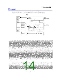
and the data buffer for the current incoming packet, although the current incoming packet is not yet
received completely. The functions of the receive DMA releasing the descriptor and the data buffer which
have been used during receiving a packet allows the software and the hardware to process the receiving
packet concurrently. This parallel processing of software and the hardware can improve the system
receiving performance significantly.
When the incoming packet is received completely, the receive DMA will write the same copy of the
packet receiving status to the first descriptor and the last descriptor of the current frame respectively. The
receiving status includes the receive completion status, the received byte count , t he r ecei ve er r or
t ype and so on. All of the status is specified in the receive descriptor R00. When the software and
hardware are concurrently processing , the software needs not to go back to read the first descriptor of the
current incoming packet for knowing the receive completed status or other receiving status when it is
processing the last descriptor and the data buffer of the current incoming packet. I f there is only one
descriptor needed for the current incoming packet, all of receiving status will be updated in the unique
descriptor.
The W89C840F transmit DMA function performs the data transfer from the host memory through
on-chip PCI bus master into the internal 2 Kbytes transmit FIFO. The transmit DMA state machine will
request the MAC to send out the data in the FIFO onto the MII.
The transmit descriptor is used to set the transmit configuration and to point to the transmit data
buffer locations. Each packet to be transmitted can be described by one or more than one descriptor. Each
descriptor consists of four consecutive long words. The first long word(T00) is for the transmit frame status
register. The T00 describes the descriptor access right control, the packet t r ansmi t t i ng st at us, etc.
The second long word(T01) is for the control register t hat
i s used to specify the transmission
configuration, including the CRC inhibit control, padding function control, and the descr i pt or
st r uct ur e cont r ol , etc. The third long word (T02) is for the first data buffer pointer and the fourth long
word is used as the second data buffer pointer in the ring structure.
The transmit descriptor list also can be constructed as a ring structure or a chain structure. The
mixed chain and ring structures also are allowed to be constructed. The scheme for constructing the
transmit descriptor list is same as the one for receiving descriptor list, but, each transmit data buffer size is
limited to under 1 Kbytes other than the 2 Kbytes receiving data buffer. In the consequence of the 1 Kbytes
transmit dat a buf f er , each descr i pt or point to a maximum of two dat a buf f er s wi t h 1 Kbyt es.
Publication Release Date:April 1997
- 15 -
Revision A1

 ETC [ ETC ]