W89C840F
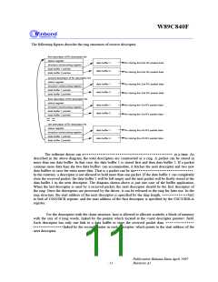
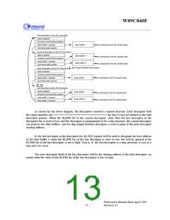
first descritpor of the RX descriptor
status register
structure constructing register
data buffer 1 pointer
data buffer 1
for storing the first RX packet data
next descriptor pointer
second descritpor of the RX descriptor
status register
data buffer 1
data buffer 2
for storing the 2nd RX packet data
for storing the 2nd RX packet data
structure constructing register
data buffer 1 pointer
next descriptor pointer
skip length between descriptors
third descritpor of the RX descriptor
status register
structure constructing register
data buffer 1 pointer
data buffer 1
for storing the 3rd RX packet data
next descriptor pointer
last descritpor of the RX descriptor
status register
data buffer 1
data buffer 2
for storing the nth RX packet data
for storing the nth RX packet data
structure constructing register
data buffer 1 pointer
data buffer 2 pointer
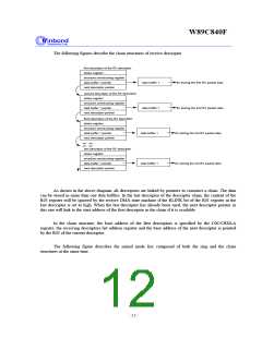
As shown by the above diagram, the descriptors construct a mixed structure. Each descriptor with
the chain structure can l i nk t o onl y one dat a buf f er i n whi ch the last 32 bits are treated as the next
descriptor pointer. When the RLINK bit of the current descriptor, other than the last descriptor in the
descriptor list, is reset to low and this descriptor is programmed to be a ring structure, the current descriptor
can point to two data buffers, and the skip length between descriptor is used to point to the next descriptor
starting address.
In the last descriptor in the descriptor list, the R03 register will be used to designate the base address
of the data buffer 2 while the RLINK bit of the last descriptor is reset to low, but will be ignored if the
RLINK bit of the last descriptor is set to high. That is, if the last descriptor is a ring structure, it acts as a
ring and vice versa.
The next descriptor field of the last descriptor will be the starting address of the first descriptor, no
matter what the value of the RLINK bit of the last descriptor is low or high.
Publication Release Date:April 1997
- 13 -
Revision A1

 ETC [ ETC ]