BRIGHT
Microelectronics
Inc.
Preliminary BM29F040
DQ2 Toggle Bit II
The BM29F040 also features the "Toggle Bit II" as a method to indicate to the host system whether a
specific sector is actively erasing or whether the sector is erase-suspended. The Toggle Bit II is valid
after the rising edge of the final WE pulse in the command sequence.
DQ2 toggles when the host system reads addresses within a sector that have been selected for erase.
The system may use OE or WE to control the read cycles. But, DQ2 can not distinguish between a
sector erasing or erase-suspended. However, Toggle Bit DQ6 can be used to determine if a sector is
actively erasing or erase-suspended. As a result, both Toggle Bits are required for the host system to
determine the current mode information. Refer to Table 7 for a further comparison of DQ6 and DQ2.
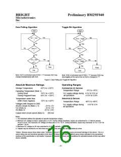
Whenever the host system begins to read the erase status using the toggle bits, they must be read at
least twice in a row. Typically, the system would store the first value and compare it to the second. If
the bits are still toggling, the system should also check DQ5(see the DQ5 description).
If DQ5 is high, the system should re-check the toggle bits since toggling may have just finished. If the
toggle bits have stopped toggling, the device has successfully completed the erase. If the toggle bits
are still toggling, the device has not successfully completed the erase operation and the host should
issue a Reset Command to the device before continuing.
If DQ5 is low, the host system should continue to monitor the toggle bits and DQ5 or issue an erase
suspend command if performing a single or multiple sector erase command.
Write Operation Status
Status
Auto-Programming
DQ7
____
DQ7
0
DQ6
DQ5
DQ3
DQ2
Standard
Toggle
0
N/A
No Toggle
Auto-Erase
Toggle
0
0
1
Toggle
Toggle
Erase
Reading an Erase
Suspended Sector
Reading a Non-Erase
Suspended Sector
Auto-Programming
Erase Suspend
No Toggle
N/A
1
Suspend
Data
Data
Data
Data
N/A
1
Data
N/A
____
DQ7
____
DQ7
0
Toggle
Toggle
Toggle
0
1
1
Exceeded
Auto-Programming
Reserved for
Future use
Time Limits
Auto-Erasing
1
Table 8. Hardware Sequence Flags
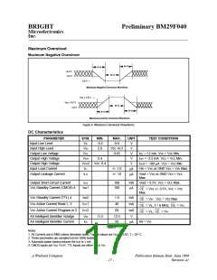
Low Vcc Write Inhibit
During Vcc power-up or power-down, a write cycle is inhibited for Vcc values of less than 3.2 Volts
(3.8 Volts typical). If Vcc < Vlko (Vlko = lock out Voltage) the command register is disabled and all
internal program/erase circuits are disabled. Under this condition the device will reset to the read
mode. If a write command is given during Vcc < Vlko, the writes will be ignored. It is the users
responsibility to ensure that the control pins are logically correct to prevent unintentional writes when
Vcc > Vlko.
A Winbond Company
Publication Release Date: June 1999
Revision A1
- 13 -

 WINBOND [ WINBOND ]