address select pins ADD1 and ADD0, and are set by con-
necting these pins to ground for a low, (0) , to VCC for a high,
(1), or left floating (TRI-LEVEL).
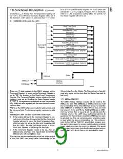
1.0 Functional Description
The LM91 temperature sensor incorporates a band-gap type
temperature sensor using a Local or Remote diode and an
8-bit ADC (Delta-Sigma Analog-to-Digital Converter). The
LM91 is compatible with the serial SMBus and I2C inter-
faces. Digital comparators compare Local and Remote read-
ings to user-programmable setpoints (LT_CRIT and
RT_CRIT). Activation of the T_CRIT_A output indicates that
a temperature reading is greater than the limit preset in a
T_CRIT register.
Therefore, the complete slave address is:
A6
A5
A4
A3
A2
A1
A0
MSB
LSB
and is selected as follows:
Address Select Pin State
LM91 SMBus Slave
Address
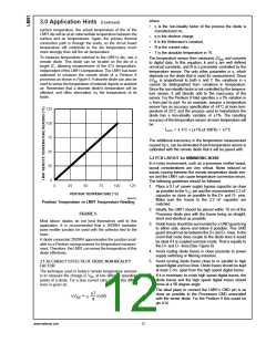
1.1 T_CRIT_A OUTPUT, T_CRIT LIMITS
ADD0
ADD1
A6:A0 binary
001 1000
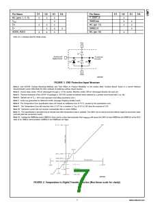
T_CRIT_A is activated when the Local temperature reading
is greater than the limit preset in the local critical temperature
setpoint register (LT_CRIT) or when the Remote tempera-
ture reading is greater than the limit preset in the remote
critical temperature setpoint register (RT_CRIT), as shown in
Figure 3. The T_CRIT_A mask bit (bit 7 of the Configuration
Register) when set will disable the T_CRIT_A output.
0
0
0
TRI-LEVEL
001 1001
0
1
001 1010
TRI-LEVEL
0
010 1001
TRI-LEVEL
TRI-LEVEL
010 1010
TRI-LEVEL
1
010 1011
The Status Register can be read to determine which event
caused the alarm. A bit in the Status Register is set high to
indicate T_CRIT temperature alarm, see Section 1.8.3.
1
1
1
0
100 1100
TRI-LEVEL
1
100 1101
Local and remote temperature diodes are sampled alter-
nately by the A/D converter. The T_CRIT_A output and the
Status Register flags are updated at the completion of a
conversion, which takes approximately 60 ms. T_CRIT_A
and the Status Register flags are reset only after the Status
Register is read and if the temperature is below the setpoint.
100 1110
The LM91 latches the state of the address select pins during
the first read or write on the SMBus. Changing the state of
the address select pins after the first read or write to any
device on the SMBus will not change the slave address of
the LM91.
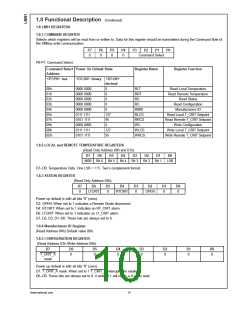
1.4 TEMPERATURE DATA FORMAT
Temperature data can be read from the Local Temperature,
Remote Temperature, and T_CRIT setpoint registers. Tem-
perature data can only be written to the T_CRIT setpoint
registers. Temperature data is represented by an 8-bit, two’s
complement byte with an LSB (Least Significant Bit) equal to
1˚C:
Temperature
Digital Output
Binary
Hex
7Dh
19h
01h
00h
FFh
E7h
C9h
+125˚C
+25˚C
+1˚C
0111 1101
0001 1001
0000 0001
0000 0000
1111 1111
1110 0111
1100 1001
20034306
FIGURE 3. T_CRIT_A Temperature Response Diagram
0˚C
1.2 POWER-ON RESET DEFAULT STATES
LM91 always powers up to these known default states:
1. Local Temperature set to 0˚C
−1˚C
−25˚C
−55˚C
2. Remote Temperature set to 0˚C until the LM91 senses a
diode present or open circuit on the D+ and D− input
pins.
1.5 OPEN-DRAIN OUTPUTS
3. Status Register set to 00h.
SMBData and T_CRIT_A outputs are open-drain and do not
have internal pull-ups. A “high” level will not be observed on
these pins until pull-up current is provided from some exter-
nal source, typically a pull-up resistor. Choice of resistor
value depends on many system factors but, in general, the
pull-up resistor should be as large as possible. This will
minimize any local temperature reading errors due to self
heating of the LM91. The maximum resistance of the pull-up,
based on LM91 specification for High Level Output Current,
to provide a 2V high level, is 30 kΩ.
4. Command Register set to 00h; T_CRIT_A enabled.
5. Local T_CRIT set to 127˚C and Remote T_CRIT set to
95˚C.
1.3 SMBus INTERFACE
The LM91 operates as a slave on the SMBus, so the
SMBCLK line is an input (no clock is generated by the LM91)
and the SMBData line is bi-directional. According to SMBus
specifications, the LM91 has a 7-bit slave address. Bit 4 (A3)
of the slave address is hard wired inside the LM91 to a 1.
The remainder of the address bits are controlled by the
1.6 DIODE FAULT DETECTION
Before each remote conversion the LM91 goes through an
external diode fault detection sequence. If the D+ input is
www.national.com
8

 OKI [ OKI ELECTRONIC COMPONETS ]