1.0 Functional Description (Continued)
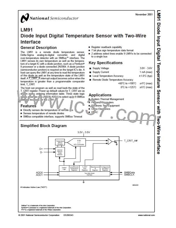
1.8 LM91 REGISTERS
1.8.1 COMMAND REGISTER
Selects which registers will be read from or written to. Data for this register should be transmitted during the Command Byte of
the SMBus write communication.
P7
P6
P5
P4
P3
P2
P1
P0
0
0
0
0
Command Select
P0-P7: Command Select:
Command Select Power On Default State
Address
Register Name
Register Function
<
>
<
>
<
>
D7:D0
P7:P0 hex
D7:D0 binary
decimal
00h
01h
02h
03h
04h
05h
07h
09h
0Bh
0Dh
0000 0000
0000 0000
0000 0000
0000 0000
0000 0000
0111 1111
0101 1111
0000 0000
0111 1111
0101 1111
0
RLT
Read Local Temperature
Read Remote Temperature
Read Status
0
RRT
RS
0
0
RC
Read Configuration
0
RMID
RLCS
RRCS
WC
Manufacturers ID
127
95
0
Read Local T_CRIT Setpoint
Read Remote T_CRIT Setpoint
Write Configuration
127
95
WLCS
WRCS
Write Local T_CRIT Setpoint
Write Remote T_CRIT Setpoint
1.8.2 LOCAL and REMOTE TEMPERATURE REGISTERS
(Read Only Address 00h and 01h):
D7
D6
D5
D4
D3
Bit 3
D2
D1
Bit 1
D0
MSB Bit 6
Bit 5
Bit 4
Bit 2
LSB
D7–D0: Temperature Data. One LSB = 1˚C. Two’s complement format.
1.8.3 STATUS REGISTER
(Read Only Address 02h):
D7
D6
D5
D4
D3
D2
OPEN
D1
D0
0
LTCRIT
0
RTCRIT
0
0
0
Power up default is with all bits “0” (zero).
D2: OPEN: When set to 1 indicates a Remote Diode disconnect.
D4: RTCRIT: When set to 1 indicates an RT_CRIT alarm.
D6: LTCRIT: When set to 1 indicates an LT_CRIT alarm.
D7, D5, D3, D1–D0: These bits are always set to 0.
1.8.4 Manufacturers ID Register
(Read Address 04h) Default value 00h.
1.8.5 CONFIGURATION REGISTER
(Read Address 03h /Write Address 09h):
D7
D6
D5
D4
D3
D2
D1
D0
T_CRIT_A
mask
0
0
0
0
0
0
0
Power up default is with all bits “0” (zero).
D7: T_CRIT_A mask: When set to 1 T_CRIT_A interrupts are masked.
D6–D0: These bits are always set to 0. A write of 1 will return a 0 when read.
www.national.com
10

 OKI [ OKI ELECTRONIC COMPONETS ]