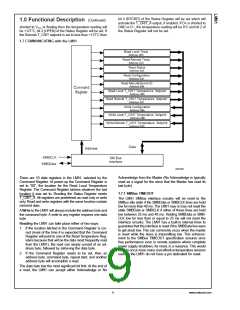
where:
3.0 Application Hints (Continued)
•
η is the non-ideality factor of the process the diode is
surface temperature, the actual temperature of the of the
LM91 die will be at an intermediate temperature between the
surface and air temperatures. Again, the primary thermal
conduction path is through the leads, so the circuit board
temperature will contribute to the die temperature much
more strongly than will the air temperature.
manufactured on,
•
•
•
•
q is the electron charge,
k is the Boltzmann’s constant,
N is the current ratio,
T is the absolute temperature in ˚K.
To measure temperature external to the LM91’s die, use a
remote diode. This diode can be located on the die of a
target IC, allowing measurement of the IC’s temperature,
independent of the LM91’s temperature. The LM91 has been
optimized to measure the remote diode of a Pentium II
processor as shown in Figure 5. A discrete diode can also be
used to sense the temperature of external objects or ambient
air. Remember that a discrete diode’s temperature will be
affected, and often dominated, by the temperature of its
leads.
The temperature sensor then measures ∆VBE and converts
to digital data. In this equation, k and q are well defined
universal constants, and N is a parameter controlled by the
temperature sensor. The only other parameter is η, which
depends on the diode that is used for measurement. Since
∆VBE is proportional to both η and T, the variations in η
cannot be distinguished from variations in temperature.
Since the non-ideality factor is not controlled by the tempera-
ture sensor, it will directly add to the inaccuracy of the
±
sensor. For the Pentium II Intel specifies a 1% variation in
η from part to part. As an example, assume a temperature
±
sensor has an accuracy specification of 4˚C at room tem-
perature of 25˚C and the process used to manufacture the
±
diode has a non-ideality variation of 1%. The resulting
accuracy of the temperature sensor at room temperature will
be:
± ± ±
4˚C + ( 1% of 298˚K) = 7˚C
TACC
=
.
The additional inaccuracy in the temperature measurement
caused by η, can be eliminated if each temperature sensor is
calibrated with the remote diode that it will be paired with.
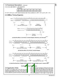
3.2 PCB LAYOUT for MINIMIZING NOISE
In a noisy environment, such as a processor mother board,
layout considerations are very critical. Noise induced on
traces running between the remote temperature diode sen-
sor and the LM91 can cause temperature conversion errors.
The following guidelines should be followed:
1. Place a 0.1 µF power supply bypass capacitor as close
as possible to the VCC pin and the recommended 2.2 nF
capacitor as close as possible to the D+ and D− pins.
Make sure the traces to the 2.2 nF capacitor are
matched.
20034316
Pentium Temperature vs LM91 Temperature Reading
2. Ideally, the LM91 should be placed within 10 cm of the
Processor diode pins with the traces being as straight,
short and identical as possible.
FIGURE 5.
Most silicon diodes do not lend themselves well to this
application. It is recommended that a 2N3904 transistor
base emitter junction be used with the collector tied to the
base.
3. Diode traces should be surrounded by a GND guard ring
to either side, above and below if possible. This GND
guard should not be between the D+ and D− lines. In the
event that noise does couple to the diode lines it would
be ideal if it is coupled common mode. That is equally to
the D+ and D− lines.(See Figure 6)
A diode connected 2N3904 approximates the junction avail-
able on a Pentium microprocessor for temperature measure-
ment. Therefore, the LM91 can sense the temperature of this
diode effectively.
4. Avoid routing diode traces in close proximity to power
supply switching or filtering inductors.
5. Avoid running diode traces close to or parallel to high
speed digital and bus lines. Diode traces should be kept
at least 2 cm. apart from the high speed digital traces.
3.1 ACCURACY EFFECTS OF DIODE NON-IDEALITY
FACTOR
The technique used in today’s remote temperature sensors
is to measure the change in VBE at two different operating
points of a diode. For a bias current ratio of N:1, this differ-
ence is given as:
6. If it is necessary to cross high speed digital traces, the
diode traces and the high speed digital traces should
cross at a 90 degree angle.
7. The ideal place to connect the LM91’s GND pin is as
close as possible to the Processors GND associated
with the sense diode. For the Pentium II this would be
pin A14.
www.national.com
12

 OKI [ OKI ELECTRONIC COMPONETS ]