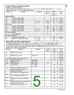
Logic Electrical Characteristics
DIGITAL DC CHARACTERISTICS
Unless otherwise noted, these specifications apply for VCC=+3.0 to 3.6 Vdc. Boldface limits apply for TA = TJ = TMIN to
TMAX; all other limits TA= TJ=+25˚C, unless otherwise noted.
Symbol Parameter
Conditions
Typical
LM91D
Limits
Units
(Note 6)
(Limit)
(Note 7)
SMBData, SMBCLK
VIN(1)
VIN(0)
IIN(1)
Logical “1” Input Voltage
Logical “0”Input Voltage
2.1
0.8
V (min)
V (max)
µA (max)
µA (max)
Logical “1” Input Current
Logical “0” Input Current
VIN = VCC
0.005
1.0
IIN(0)
VIN = 0V
−0.005
−1.0
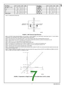
ADD0, ADD1
VIN(1)
VIN(0)
IIN(1)
Logical “1” Input Voltage
Logical “0”Input Voltage
Logical “1” Input Current
Logical “0” Input Current
VCC
GND
50
1.6
0.5
V (min)
V (max)
µA (max)
µA (max)
VIN = VCC
VIN = 0V
600
600
IIN(0)
50
ALL DIGITAL INPUTS
CIN
Input Capacitance
20
pF
ALL DIGITAL OUTPUTS
IOH
High Level Output Current
SMBus Low Level Output Voltage
VOH = VCC
IOL = 3 mA
IOL = 6 mA
100
0.4
0.6
µA (max)
V (max)
VOL
SMBus DIGITAL SWITCHING CHARACTERISTICS
Unless otherwise noted, these specifications apply for VCC=+3.0 Vdc to +3.6 Vdc, CL (load capacitance) on output lines = 80
pF. Boldface limits apply for TA = TJ = TMIN to TMAX; all other limits TA = TJ = +25˚C, unless otherwise noted.
The switching characteristics of the LM91 fully meet or exceed the published specifications of the SMBus or I2C bus. The fol-
lowing parameters are the timing relationships between SMBCLK and SMBData signals related to the LM91. They are not nec-
essarily the I2C or SMBus bus specifications.
Symbol
Parameter
SMBus Clock Frequency
SMBus Clock Low Time
Conditions
Typical
Limits
(Note 7)
400
Units
(Limit)
(Note 6)
fSMB
kHz (max)
kHz (min)
µs (min)
ms (max)
ms (max)
µs (min)
µs
10
tLOW
10% to 10%
1.3
25
t
LOWSEXT Cumulative Clock Low Extend Time
25
tHIGH
tR;SMB
tF;SMB
tOF
SMBus Clock High Time
SMBus Rise Time
SMBus Fall Time
90% to 90%
10% to 90%
90% to 10%
CL = 400 pF
IO = 3 mA
0.6
1
0.3
µs
Output Fall Time
250
ns (max)
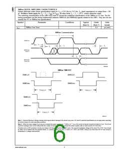
tTIMEOUT
SMBData and SMBCLK Time Low for
Reset of Serial Interface (Note 12)
SMBCLK (Clock) Period
25
40
ms (min)
ms (max)
µs (min)
ns (min)
t1
2.5
100
t2,
Data In Setup Time to SMBCLK High
tSU;DAT
t3,
tHD;DAT
t4,
tHD;STA
t5,
tSU;STO
t6,
Data Out Stable after SMBCLK Low
0
ns (min)
µs (max)
ns (min)
0.9
100
SMBData Low Setup Time to SMBCLK
Low
SMBData High Delay Time after SMBCLK
High (Stop Condition Setup)
SMBus Start-Condition Setup Time
100
0.6
ns (min)
µs (min)
tSU;STA
5
www.national.com

 OKI [ OKI ELECTRONIC COMPONETS ]