Pin Name
NC (pins 1, 5, 9)
VCC
D1
D2
D3
x
D4
Pin Name
T_CRIT_A
SMBData
NC (pin 13)
SMBCLK
D1
D2
x
D3
D4
x
x
x
x
x
x
x
D+
x
x
x
x
x
x
x
D−
x
x
ADD0, ADD1
x
NC (pin 16)
x
Note: An x indicates that the diode exists.
20034308
FIGURE 1. ESD Protection Input Structure
Note 3: See AN-450 “Surface Mounting Methods and Their Effect on Product Reliability” or the section titled “Surface Mount” found in a current National
Semiconductor Linear Data Book for other methods of soldering surface mount devices.
Note 4: Human body model, 100 pF discharged through a 1.5 kΩ resistor. Machine model, 200 pF discharged directly into each pin.
Note 5: Thermal resistance of the QSOP-16 package is 130˚C/W, junction-to-ambient when attached to a printed circuit board with 2 oz. foil.
Note 6: Typicals are at T = 25˚C and represent most likely parametric norm.
A
Note 7: Limits are guaranteed to National’s AOQL (Average Outgoing Quality Level).
±
Note 8: The Temperature Error specification does not include an additional error of 1˚C, caused by the quantization error.
±
Note 9: The Temperature Error will vary less than 1.0˚C for a variation in V
of 3V to 3.6V from the nominal of 3.3V.
CC
Note 10: Quiescent current will not increase substantially with an active SMBus.
Note 11: This specification is provided only to indicate how often temperature data is updated. The LM91 can be read at any time without regard to conversion state
(and will yield last conversion result).
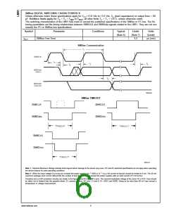
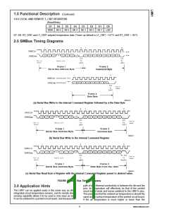
Note 12: Holding the SMBData and/or SMBCLK lines Low for a time interval greater than t
will cause the LM91 to reset SMBData and SMBCLK to the IDLE
TIMEOUT
state of an SMBus communication (SMBCLK and SMBData set High).
20034305
FIGURE 2. Temperature-to-Digital Transfer Function (Non-linear scale for clarity)
7
www.national.com

 OKI [ OKI ELECTRONIC COMPONETS ]