VT82C686B
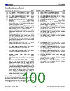
Power Management I/O-Space Registers
Basic Power Management Control and Status
I/O Offset 1-0 - Power Management Status.................RWC
I/O Offset 3-2 - Power Management Enable .................. RW
The bits in this register are set only by hardware and can be
reset by software by writing a one to the desired bit position.
The bits in this register correspond to the bits in the Power
Management Status Register at offset 1-0.
(WAK_STS) ................... default = 0
........................................always reads 0
15 Wakeup Status
15 Reserved
This bit is set when the system is in the suspend state
and an enabled resume event occurs. Upon setting
this bit, the system automatically transitions from the
suspend state to the normal working state (from C3 to
C0 for the processor).
........................................ always reads 0
........................................always reads 0
........................................always reads 0
(RTC_EN)............................default = 0
14-12 Reserved
14-12 Reserved
11 Reserved
10 RTC Enable
(APO_STS)........... default = 0
11 Abnormal Power-Off
(RTC_STS)........................... default = 0
10 RTC Status
This bit is set when the RTC generates an alarm (on
assertion of the RTC IRQ signal).
This bit may be set to trigger either an SCI or an SMI
(depending on the setting of the SCI_EN bit) to be
generated when the RTC_STS bit is set.
(SB_STS)................. default = 0
This bit is set when the sleep button (SLPBTN# /
IRQ6 / GPI4) is pressed.
(SB_EN) .................default = 0
Sleep Button Enable
This bit may be set to trigger either an SCI or SMI
when the SB_STS bit is set.
9
8
Sleep Button Status
9
8
(PB_STS)............... default = 0
(PB_EN) ...............default = 0
Power Button Enable
Power Button Status
This bit is set when the PWRBTN# signal is asserted
LOW. If the PWRBTN# signal is held LOW for
more than four seconds, this bit is cleared and the
system will transition into the soft off state.
This bit may be set to trigger either an SCI or an SMI
(depending on the setting of the SCI_EN bit) to be
generated when the PB_STS bit is set.
........................................ always reads 0
........................................always reads 0
7-6 Reserved
7-6 Reserved
(GBL_STS)........................ default = 0
This bit is set by hardware when BIOS_RLS is set
(typically by an SMI routine to release control of the
SCI/SMI lock). When this bit is cleared by software
(by writing a one to this bit position) the BIOS_RLS
bit is also cleared at the same time by hardware.
(GBL_EN).........................default = 0
This bit may be set to trigger either an SCI or an SMI
(depending on the setting of the SCI_EN bit) to be
generated when the GBL_STS bit is set.
5
Global Status
5
Global Enable
........................................always reads 0
(BM_STS) ................. default = 0
Bus Master Status
4
Reserved
4
This bit is set when a system bus master requests the
system bus. All PCI master, ISA master and ISA
DMA devices are included.
........................................always reads 0
3-1 Reserved
........................................ always reads 0
3-1 Reserved
(TMR_EN) ..............default = 0
This bit may be set to trigger either an SCI or an SMI
(depending on the setting of the SCI_EN bit) to be
generated when the TMR_STS bit is set.
0
ACPI Timer Enable
(TMR_STS).. default = 0
The bit is set when the 23rd (31st) bit of the 24 (32)
bit ACPI power management timer changes.
0
ACPI Timer Carry Status
Revision 1.71 June 9, 2000
-90-
Power Management I/O-Space Registers

 ETC [ ETC ]