The fixed memory map consists of two Monitor Command Stack
Pointers (location 102h and 106h), two Monitor Data Stack
Pointers (locations 103h and 107h), and a Selective Message
TABLE 31. TYPICAL SELECTIVE MESSAGE MONITOR
MEMORY MAP (SHOWN FOR 12K RAM)
ADDRESS
DESCRIPTION
T/R
Monitor Lookup Table (0280-02FFh) based on RT Address,
(HEX)
0000-0101
0102
, and subaddress. Assume a Monitor Command Stack size of 1K
words, and a Monitor Data Stack size of 2K words
Not Used
Monitor Command Stack Pointer A (fixed location)
Monitor Data Stack Pointer A (fixed location)
Not Used
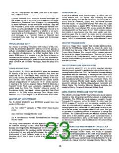
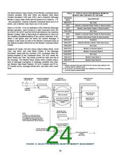
Refer to FIGURE 13 for an illustration of the Selective Message
Monitor operation. Upon receipt of a valid Command Word, the
BU-65552, BU-65551 and BU-65550 will reference the Selective
Monitor Lookup Table (a fixed block of addresses) to check for
the condition (disabled/enabled) of the current command. If dis-
abled, it will ignore (and not store) the current message; if
enabled, it will create an entry in the Monitor Command Stack at
the address location referenced by the Monitor Command Stack
Pointer.
0103
0104-0105
0106
Monitor Command Stack Pointer B (fixed location)
Monitor Data Stack Pointer B (fixed location)
Registers
0107
0260-027F
0280-02FF
0300-03FF
0400-07FF
0800-0BFF
0C00-0FFF
1000-1FFF
2000-2FFF
Selective Monitor Lookup Table (fixed area)
Not Used
Monitor Command Stack A
Monitor Command Stack B
Not Used
Similar to RT mode, The ACE stores a Block Status Word, 16-bit
Time Tag Word, and Data Block Pointer in the Message
Descriptor, along with the received 1553 Command Word fol-
lowing reception of the Command Word. The ACE writes the
Block Status and Time Tag Words at both the start and end of
the message. The Monitor Block Status Word contains indica-
tions of message in-progress or message complete, bus chan-
nel, Monitor Data Stack Rollover, RT-to-RT transfer and RT-to-
RT transfer errors, message format error, and other error condi-
tions.
Monitor Data Stack A
Monitor Data Stack B
Notes:
1) Address represents the word offset from the memory base address in the
common memory address space.
3) For the 65552, the memory spans from 0000(hex) to FFFF(hex), providing
a full 64K words of shared RAM.
CONFIGURATION
REGISTER #1
MONITOR COMMAND
STACK POINTERS
MONITOR
COMMAND STACKS
MONITOR DATA
STACKS
15
13
0
CURRENT
AREA B/A
BLOCK STATUS WORD
TIME TAG WORD
MONITOR DATA
BLOCK #N
CURRENT
COMMAND WORD
DATA BLOCK POINTER
MONITOR DATA
BLOCK #N + 1
RECEIVED COMMAND
WORD
MONITOR DATA
STACK POINTERS
NOTE
IF THIS BIT IS "0" (NOT SELECTED)
NO WORDS ARE STORED IN EITHER
THE COMMAND STACK OR DATA STACK.
IN ADDITION, THE COMMAND AND DATA
STACK POINTERS WILL NOT BE UPDATED.
SELECTIVE MONITOR
LOOKUP TABLES
OFFSET BASED ON
RTA4-RTA0, T/R, SA4
SELECTIVE MONITOR
ENABLE
(SEE NOTE)
FIGURE 13. SELECTIVE MESSAGE MONITOR MEMORY MANAGEMENT
24

 ETC [ ETC ]