TABLE 25 shows the Message Monitor Block Status Word. The
Data Block Pointer references the first word stored in the Monitor
Data Stack (the first word following the Command Word) for the
current message. The will then proceed to store the subsequent
words from the message (possible second Command Word,
Data Word(s), Status Word(s) into consecutive locations in the
Monitor Data Stack.
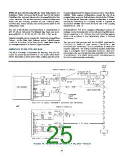
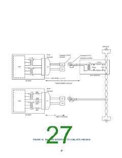
to-peak voltage levels that appear at various points (when trans-
mitting). Both coupling configurations require the use of an
included cable assembly that interfaces directly to the PC Card.
For the transformer (long stub) coupling configuration, a second
transformer, referred to as a coupling transfer is required. In
accordance with MIL-STD-1553B, the turns ratio of the coupling
transformer is 1.0 to 1.4.
The size of the Monitor Command Stack is programmable to
256, 1K, 4K, or 16K words. The Monitor Data Stack size is pro-
grammable to 512, 1K, 2K, 4K, 8K, 16K, 32K, or 64K words.
Both transformer and direct coupling configurations require an
isolation resistor to be placed in series with each leg of the trans-
former connecting to the 1553 bus; this protects the bus against
short circuit conditions in the transformers, stubs, or terminal
components.
Monitor interrupts may be enabled for Monitor Command Stack
Rollover, Monitor Data Stack Rollover, and/or End-of-Message
conditions. In addition, in the Word Monitor mode there may be
an interrupt enabled for a Monitor Trigger condition.
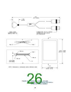
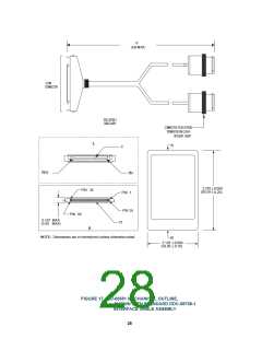
The standard cable provided with the BU-65552 (part number
DDC-70093-1), BU-65551 (part number DDC-58708-1) and
BU-65550 (part number DDC-57612) provide for a transformer
coupled connection. The mating connector required on the stub
cable is a Trompeter PL75 or equivalent connector. Direct cou-
pling requires the use of a optional cable assembly (DDC-70093-
1 for BU-65552, DDC-57613 for BU-65550, contact factory for
BU-65551 cable assembly availability).
INTERFACE TO MIL-STD-1553 BUS
FIGURES 9 through 14 illustrates the interface from the BU-
65552, BU-65551 and BU-65550 to a 1553 bus for either trans-
former (long stub) or direct (short stub) coupling, plus the peak-
DATA
BUS
Z0
TRANSFORMER COUPLED
Trompeter PL75
or equivalent connector
BUS A
1:1.4
0.75 Z0
28VP-P 7VP-P
0.75 Z0
BUS COUPLER
1:1.79
1:1.79
1
2
3
4
5
6
7
8
9
10
11
12
13
14
15
20VP-P
STUB
20 Ft. MAX
BU-65550
BUS B
Trompeter
CJ70
Cable Jack
DDC-57612-1 CABLE ASSEMBLY (furnished with BU-65550)
DIRECT COUPLED
OR
BUS A
55Ω
55Ω
1: 2.5
1
2
3
4
5
6
7
8
9
BUS B
1 Ft. MAX
55Ω
55Ω
1:2.5
10
11
12
13
14
15
Z0
DDC-57613-1 CABLE ASSEMBLY
FIGURE 14. BU-65550 INTERFACE TO A MIL-STD-1553 BUS
25

 ETC [ ETC ]