TEA1716T
NXP Semiconductors
Resonant power supply control IC with PFC
7.8.9 HBC high-frequency protection, HFP-HBC
Normally the converter does not operate continuously at maximum frequency because it
sweeps down to much lower values. Certain error conditions, such as a disconnected
transformer, can cause the converter to operate continuously at maximum frequency. If
zero-voltage switching conditions are no longer present, the MOSFETs can overheat. The
TEA1716 features High-Frequency Protection (HFP) for the HBC controller to protect it
from being damaged in such circumstances.
HFP senses the voltage across the internal resistor Rfmax. This voltage indicates the
current frequency. When the frequency is higher than 75 % of the soft start frequency
range, the protection timer is started. The 75 % level corresponds to an Rfmax voltage of
V
hfp(RFMAX) (1.83 V typical).
7.8.10 HBC overcurrent regulation and protection, OCR and OCP
(pin SNSCURHBC)
The HBC controller is protected against overcurrent in two ways:
• Overcurrent regulation (OCR-HBC) which increases the frequency slowly; the
protection timer is also started.
• Overcurrent protection (OCP-HBC) which steps to maximum frequency.
A boost voltage compensation function is included to reduce the variation in the output
current protection level.
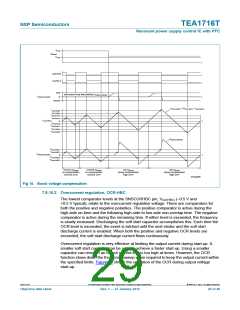
7.8.10.1 Boost voltage compensation
The primary current, also known as the resonant current, is sensed via pin SNSCURHBC.
It senses the momentary voltage across an external current sense resistor Rcur(HBC). The
use of the momentary current signal allows for fast overcurrent protection and simplifies
the stabilizing of overcurrent regulation. The OCR and OCP comparators compare
V
SNSCURHBC with the maximum positive and negative values.
For the same output power, the primary current is higher when the boost voltage is low. A
boost compensation is included to reduce the dependency of the protected output current
level on the boost voltage. The boost compensation sources and sinks a current from the
SNSCURHBC pin. This current creates a voltage drop across the series resistor Rcurcmp
.
The amplitude of the current depends linearly on the boost voltage. At nominal boost
voltage, the current is zero and the voltage VCur(HBC) across the current sense resistor is
also present at the SNSCURHBC pin. At the UVP-boost start level Vuvp(SNSBOOST), the
current is at a maximum. The direction of the current, sink or source, depends on the
active gate signal. The voltage drop created across Rcurcmp reduces the amplitude at the
pin, resulting in a higher effective current protection level. The value of Rcurcmp sets the
amount of compensation. Figure 15 shows how the boost compensation works for an
artificial current signal. The sinking compensation current only flows when VSNSCURHBC is
positive because of the circuit implementation.
TEA1716T
All information provided in this document is subject to legal disclaimers.
© NXP B.V. 2012. All rights reserved.
Objective data sheet
Rev. 1 — 27 January 2012
28 of 46

 ETC [ ETC ]