AND8327/D
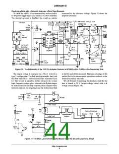
The injection voltage source is implemented with a
ChꢀB
ǒ Ǔ
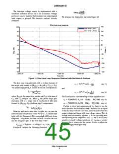
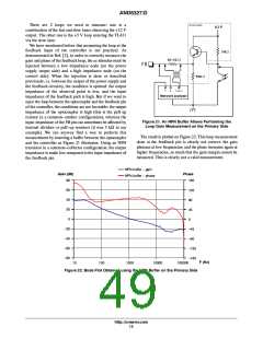
We obtained the Bode plots shown in Figure 15.
20log10
wideband isolation device and a 33 W resistor. Voltage
probes are used to measure the loop input and output signals
with respect to ground. The network analyzer directly
computes
ChꢀA
Slow lane loop response
180
144
108
72
100
80
slow lane - gain
slow lane - phase
60
40
36
20
0
0
-36
-72
-20
-40
-60
-108
-144
-180
-80
-100
1.00E+01
1.00E+02
1.00E+03
Freq (Hz)
1.00E+04
1.00E+05
Figure 15. Slow Lane Loop Response Obtained with the Network Analyzer
The slow lane loop gain starts with a -1 slope because of
the origin pole formed by (R = R +R , C = C ).
The power stage pole f is around 20 Hz and corresponds to:
p
ń20
x1 + 10A
y1 + 10A
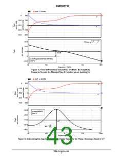
cosǒö
Ǔ
1
(eq. 11)
(eq. 12)
1 180
upper
12
10 zero
6
p
and
1
fp +
p
ń20
sinǒö
Ǔ
1
pRloadCout
1 180
where R
C
is the output load resistor and C is the sum of
out
The Excel syntax corresponding to these equations are:
load
and C (Figure 13). After f , the power stage gain
5b p
5a
x1 + POWER(10;A1ń20) @ COS(ö1 @ PI()ń180) (eq. 13)
decreases with a -2 slope until it reaches the 8 kHz pole
formed by (R , C ) of our type 2 compensator:
x2 + POWER(10;A1ń20) @ SIN(ö1 @ PI()ń180) (eq. 14)
pullup pole
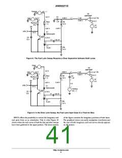
Further to slow lane measurement, we have to run the
same operation for the fast lane loop. We inject the ac signal
in the fast lane while the slow lane is disconnected from the
output voltage and biased with a dc voltage source. This dc
voltage must be manually adjusted to fix the operating point
corresponding to the output load used. As the TL431 is very
sensitive to small voltage variations, we can use a resistor
between the dc source and the resistor divider to adjust the
output voltage (See Figure 16).
1
fpc
+
2pRpullupCpole
Now that we have the slow lane loop plot, we can paste the
network analyzer data into excel. We have a 3-column data
table with the frequency (Hz), magnitude (dB) and phase
(degrees). Using Euler notation, we will calculate the real
and the imaginary part of the slow lane vector:
(eq. 10)
Vout,slow + A1(cosö1 ) j sin ö1) + x1 ) jꢁy1
Excel will compute the following formulas:
http://onsemi.com
9

 ETC [ ETC ]