NCP1271
Besides the timer−based fault detection, the NCP1271
also enters fault condition when V drops below V
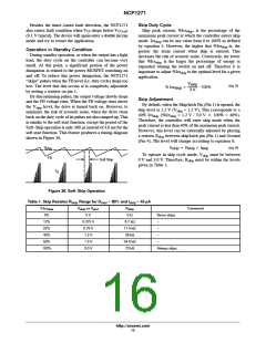
Skip Duty Cycle
Skip peak current, %Ics , is the percentage of the
)
(off
CC
CC
skip
(9.1 V typical). The device will again enter a double hiccup
mode and try to restart the application.
maximum peak current at which the controller enters skip
mode. Ics
can be any value from 0 to 100% as defined
skip
by equation 5. However, the higher that %Ics
greater the drain current when skip is entered. This
increases the risk of acoustic noise. Conversely, the lower
is, the
skip
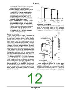
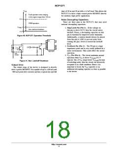
Operation in Standby Condition
During standby operation, or when the output has a light
load, the duty cycle on the controller can become very
small. At this point, a significant portion of the power
dissipation is related to the power MOSFET switching on
and off. To reduce this power dissipation, the NCP1271
“skips” pulses when the FB level (i.e. duty cycle) drops too
low. The level that this occurs at is completely adjustable
by setting a resistor on pin 1.
that %Ics
is the larger the percentage of energy is
skip
expended turning the switch on and off. Therefore it is
important to adjust %Ics
application.
to the optimal level for a given
skip
V
skip
(eq. 5)
% Ics
+
· 100%
skip
3 V
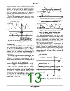
By discontinuing pulses, the output voltage slowly drops
and the FB voltage rises. When the FB voltage rises above
Skip Adjustment
By default, when the Skip/latch Pin (Pin 1) is opened, the
skip level is 1.2 V (V = 1.2 V). This corresponds to a
the V
level, the drive is turned back on. However, to
skip
skip
minimize the risk of acoustic noise, when the drive turns
back on the duty cycle of its pulses are also ramped up. This
is similar to the soft start function, except the period of the
Soft−Skip operation is only 300 ms instead of 4.0 ms for the
soft start function. This feature produces a timing diagram
shown in Figure 36.
40% Ics
(%Ics
= 1.2 V / 3.0 V 100% = 40%).
skip
skip
Therefore, the controller will enter skip mode when the
peak current is less than 40% of the maximum peak current.
However, this level can be externally adjusted by placing
a resistor R
between skip/latch pin (Pin 1) and Ground
skip
(Pin 4). The level will change according to equation 6.
V
skip
V + R
skip skip
I
skip
(eq. 6)
To operate in skip cycle mode, V
must be between
skip
FB
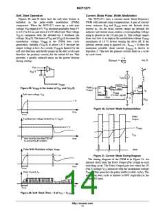
Soft Skip
0 V and 3.0 V. Therefore, R
must be within the levels
skip
given in Table 1.
I
D
Figure 36. Soft−Skip Operation
Table 1. Skip Resistor Rskip Range for Dmax = 80% and Iskip = 43 mA
%Ics
V
skip
or V
R
skip
Comment
skip
pin1
0%
0 V
0 W
Never skips.
12%
25%
40%
50%
100%
0.375 V
0.75 V
1.2 V
8.7 kW
17.4 kW
28 kW
−
−
−
1.5 V
34.8 kW
70 kW
−
3.0 V
Always skips.
http://onsemi.com
15

 ETC [ ETC ]