LD7575
Application Information
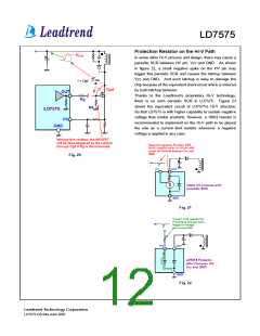
threshold thus the current source is on to supply a current
with 1mA. Meanwhile, the Vcc supply current is as low as
100µA thus most of the HV current is utilized to charge the
Vcc capacitor. By using such configuration, the turn-on
delay time will be almost same no matter under low-line or
high-line conditions.
Operation Overview
As long as the green power requirement becomes a trend
and the power saving is getting more and more important for
the switching power supplies and switching adaptors, the
traditional PWM controllers are not able to support such new
requirements. Furthermore, the cost and size limitation force
the PWM controllers need to be powerful to integrate more
functions to reduce the external part counts. The LD7575
is targeted on such application to provide an easy and cost
effective solution; its detail features are described as below:
Whenever the Vcc voltage is higher than UVLO(on) to
power on the LD7575 and further to deliver the gate drive
signal, the high-voltage current source is off and the supply
current is provided from the auxiliary winding of the
transformer. Therefore, the power losses on the startup
circuit can be eliminated and the power saving can be easily
achieved.
Internal High-Voltage Startup Circuit and
Under Voltage Lockout (UVLO)
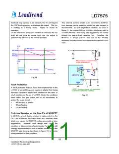
An UVLO comparator is included to detect the voltage on
the Vcc pin to ensure the supply voltage enough to power
on the LD7575 PWM controller and in addition to drive the
power MOSFET. As shown in Fig. 14, a hysteresis is
provided to prevent the shutdown from the voltage dip
during startup. The turn-on and turn-off threshold level are
set at 16V and 10.0V, respectively.
Vin
Cbulk
D1
R1
C1
Vcc
HV
VCC
OUT
UVLO(on)
UVLO(off)
LD7575
Comp
CS
GND
Rs
t
Fig. 13
HV Current
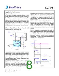
Traditional circuit powers up the PWM controller through a
startup resistor to provide the startup current. However, the
startup resistor consumes significant power which is more
and more critical whenever the power saving requirement is
coming tight. Theoretically, this startup resistor can be
very high resistance value. However, higher resistor value
will cause longer startup time.
1mA
~ 0mA (off)
t
Vcc current
Operating Current
(Supply from Auxiliary Winding)
To achieve an optimized topology, as shown in figure 13,
LD7575 implements a high-voltage startup circuit for such
requirement. During the startup, a high-voltage current
source sinks current from the bulk capacitor to provide the
startup current as well as charge the Vcc capacitor C1.
During the startup transient, the Vcc is lower than the UVLO
Startup Current
(<100uA)
Fig. 14
8
Leadtrend Technology Corporation
LD7575-DS-04a June 2007

 ETC [ ETC ]