LD7575
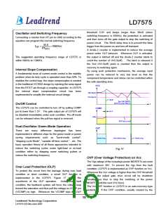
threshold 5.0V and keeps longer than 30mS (when
switching frequency is 65KHz), the protection is activated
and then turns off the gate output to stop the switching of
power circuit. The 30mS delay time is to prevent the false
trigger from the power-on and turn-off transient.
Oscillator and Switching Frequency
Connecting a resistor from RT pin to GND according to the
equation can program the normal switching frequency:
65.0
f
=
×100(KHz)
SW
RT
(KΩ)
A divide-2 counter is implemented to reduce the average
power under OLP behavior. Whenever OLP is activated,
the output is latched off and the divide-2 counter starts to
count the number of UVLO(off). The latch is released if
the 2nd UVLO(off) point is counted then the output is
recovery to switching again.
The suggested operating frequency range of LD7575 is
within 50KHz to 130KHz.
Internal Slope Compensation
By using such protection mechanism, the average input
power can be reduced to very low level so that the
component temperature and stress can be controlled within
the safe operating area.
A fundamental issue of current mode control is the stability
problem when its duty-cycle is operated more than 50%. To
stabilize the control loop, the slope compensation is needed
in the traditional UC384X design by injecting the ramp signal
from the RT/CT pin through a coupling capacitor. In LD7575,
the internal slope compensation circuit has been
implemented to simplify the external circuit design.
On/Off Control
The LD7575 can be controlled to turn off by pulling COMP
pin to lower than 1.2V. The gate output pin of LD7575 will
be disabled immediately under such condition. The off mode
can be released when the pull-low signal is removed.
Dual-Oscillator Green-Mode Operation
There are many difference topologies has been
implemented in different chips for the green-mode or power
saving requirements such as “burst-mode control”,
“skipping-cycle Mode”, “variable off-time control “…etc. The
basic operation theory of all these approaches intended to
reduce the switching cycles under light-load or no-load
condition either by skipping some switching pulses or
reduce the switching frequency.
Fig. 17
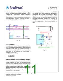
OVP (Over Voltage Protection) on Vcc
The Vgs ratings of the nowadays power MOSFETs are most
with maximum 30V. To prevent the Vgs from the fault
condition, LD7575 is implemented an OVP function on Vcc.
Whenever the Vcc voltage is higher than the OVP threshold
voltage, the output gate drive circuit will be shutdown
simultaneous thus to stop the switching of the power
MOSFET until the next UVLO(on).
Over Load Protection (OLP)
To protect the circuit from the damage during over load
condition or short condition, a smart OLP function is
implemented in the LD7575. Figure 17 shows the
waveforms of the OLP operation.
Under such fault
condition, the feedback system will force the voltage loop
toward the saturation and thus pull the voltage on COMP pin
(VCOMP) to high. Whenever the VCOMP trips the OLP
The Vcc OVP function in LD7575 is an auto-recovery type
protection. If the OVP condition, usually caused by the
10
Leadtrend Technology Corporation
LD7575-DS-04a June 2007

 ETC [ ETC ]