LD7575
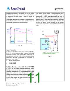
feedback loop opened, is not released, the Vcc will tripped
the OVP level again and re-shutdown the output. The Vcc
is working as a hiccup mode. Figure 18 shows its
operation.
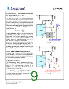
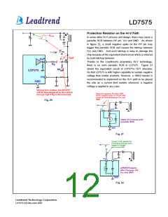
This external pull-low resistor is to prevent the MOSFET
from damage during power-on under the gate resistor is
disconnected. In such single-fault condition, as show in
figure 21, the resistor R8 can provide a discharge path to
avoid the MOSFET from being false-triggered by the current
through the gate-to-drain capacitor Cgd. Therefore, the
MOSFET is always pull-low and kept in the off-state
whenever the gate resistor is disconnected or opened in any
case.
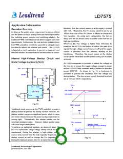
On the other hand, if the OVP condition is removed, the Vcc
level will get back to normal level and the output is
automatically returned to the normal operation.
VCC
OVP Tripped
OVP Level
UVLO(on)
UVLO(off)
t
OUT
Non-Switching
Switching
Switching
t
Fig. 18
Fault Protection
A lot of protection features have been implemented in the
LD7575 to prevent the power supply or adapter from being
damaged caused by single fault condition on the open or
short condition on the pin of LD7575. Under the conditions
listed below, the gate output will be off immediately to
protect the power circuit ---
Fig. 19
y
y
y
RT pin short to ground
RT pin floating
CS pin floating
Pull-Low Resistor on the Gate Pin of MOSFET
In LD7575, an anti-floating resistor is implemented on the
OUT pin to prevent the output from any uncertain state
which may causes the MOSFET working abnormally or false
triggered-on.
However, such design won’t cover the
condition of disconnection of gate resistor Rg thus it is still
strongly recommended to have a resistor connected on the
MOSFET gate terminal (as shown in figure 19) to provide
extra protection for fault condition.
11
Leadtrend Technology Corporation
LD7575-DS-04a June 2007

 ETC [ ETC ]