ICL8052A/ICL71C03, ICL8068A/ICL71C03
RUN/HOLD (PIN 4)
BUSY (PIN 28)
When high (or open) the A/D will free-run with equally
spaced measurement cycles every 40,0002/4,002 clock
pulses. If taken low, the converter will continue the full
measurement cycle that it is doing and then hold this reading
as long as Pin 4 is held low. A short positive pulse (greater
then 300ns) will now initiate a new measurement cycle
beginning with up to 10,001/1,001 counts of auto zero. Of
course if the pulse occurs before the full measurement cycle
(40,002/4,002 counts) is completed, it will not be recognized
and the converter will simply complete the measurement it is
doing. An external indication that full measurement cycle
has been completed is that the first STROBE pulse (see
below) will occur 101/11 counts after the end of this cycle.
Thus, if RUN/HOLD is low and has been low for at least
101/11 counts, converter is holding and ready to start a new
measurement when pulsed high.
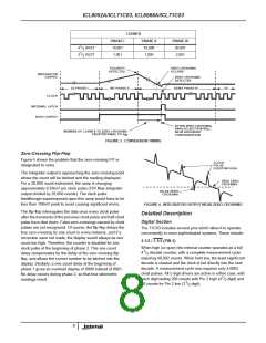
BUSY goes high at the beginning of signal integrate and
stays high until the first clock pulse after zero-crossing (or
after end of measurement in the case of an OVER-RANGE).
The internal latches are enabled (i.e., loaded) during the first
clock pulse after BUSY and are latched at the end of this
clock pulse. The circuit automatically reverts to auto-zero
when not BUSY so it may also be considered an A-Z signal.
A very simple means for transmitting the data down a single
wire pair from a remote location would be to AND BUSY with
clock and subtract 10,001/1,001 counts from the number of
pulses received - as mentioned previously there is one “NO-
count” pulse in each Reference Integrate cycle.
OVER-RANGE (PIN 4)
This pin goes positive when the input signal exceeds the
range (20,000/2,000) of the converter. The output F-F is set
at the end of BUSY and is reset to zero at the beginning of
Reference Integrate in the next measurement cycle.
STROBE (PIN 18)
This is a negative-going output pulse that aids in transferring
the BCD data to external latches, UARTs or
UNDER-RANGE (PIN 13)
This pin goes positive when the reading is 9% of range or
less. The output F-F is set at the end of BUSY (if the new
reading is 1800/180 or less) and is reset a the beginning of
Signal Integrate of the next reading.
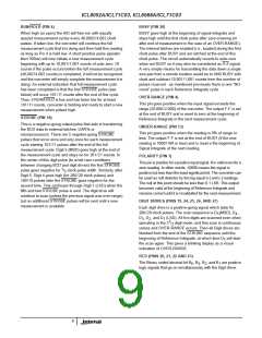
microprocessors. There are 5 negative-going STROBE
pulses that occur once and only once for each measurement
cycle starting 101/11 pulses after the end of the full
measurement cycle. Digit 5 (MSD) goes high at the end of
the measurement cycle and stays on for 201/21 counts. In
the center of this digit pulse (to avoid race conditions
POLARITY (PIN 3)
This pin is positive for a positive input signal. It is valid even for a
zero reading. In other words, +0000 means the signal is
positive but less than the least significant bit. The converter can
be used as null detector by forcing equal (+) and (-) readings.
The null at this point should be less than 0.1 LSB. This output
becomes valid at the beginning of Reference Integrate and
remains correct until it is revalidated for the next measurement.
between changing BCD and digit drives) the first STROBE
1
pulse goes negative for / clock pulse width. Similarly, after
2
Digit 5, Digit 4 goes high (for 200/20 clock pulses) and
100/10 pulses later the STROBE goes negative for the
second time. This continues through Digit 1 (LSD) when the
fifth and last STROBE pulse is sent. The digit drive will
continue to scan (unless the previous signal was over-range)
but no additional STROBE pulses will be sent until a new
measurement is available.
DIGIT DRIVES (PINS 19, 24, 25, 26, AND 27)
Each digit drive is a positive-going signal which lasts for
200/20 clock pulses. The scan sequence is D (MSD), D ,
5
4
D , D , and D (LSD). All five digits are scanned even when
3
2
1
1
operating in the 3 / digit mode, and this scan is continuous
2
unless and OVER-RANGE occurs. Then all Digit drives are
blanked from the end of the STROBE sequence until the
beginning of Reference Integrate, at which time D will start
5
the scan again. This gives a blinking display as a visual
indication of OVER-RANGE.
BCD (PINS 20, 21, 22 AND 23)
The Binary coded decimal bit B , B , B , and B are positive
8
4
2
1
logic signals that go on simultaneously with the Digit driver.
9

 ETC [ ETC ]