ICL8052A/ICL71C03, ICL8068A/ICL71C03
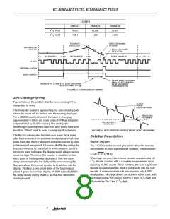
COUNTS
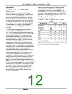
PHASE I
10,001
1,001
PHASE II
10,000
1,000
PHASE III
20,001
1
4 / DIGIT
2
1
3 / DIGIT
2,001
2
POLARITY
DETECTED
ZERO CROSSING
OCCURS
INTEGRATOR
OUTPUT
ZERO CROSSING
DETECTED
AZ PHASE I
INT PHASE II
DEINT PHASE III
AZ
CLOCK
INTERNAL LATCH
BUSY OUTPUT
AFTER ZERO CROSSING,
ANALOG SECTION WILL
BE IN AUTOZERO
NUMBER OF COUNTS TO ZERO CROSSING
PROPORTIONAL TO V
IN
CONFIGURATION
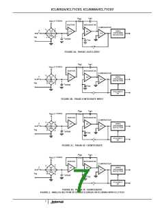
FIGURE 3. CONVERSION TIMING
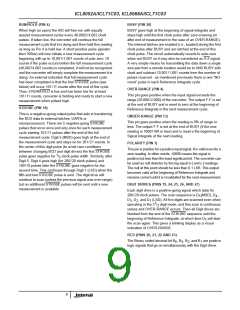
Zero-Crossing Flip-Flop
Figure 4 shows the problem that the zero-crossing F/F is
designated to solve.
CLOCK
PULSE
FEEDTHROUGH
The integrator output is approaching the zero-crossing point
where the count will be latched and the reading displayed.
For a 20,000 count instrument, the ramp is changing
approximately 0.50mV per clock pulse (10V Max integrator
output divided by 20,000 counts). The clock pulse
TRUE ZERO
CROSSING
FALSE ZERO
CROSSING
feedthrough superimposed upon this ramp would have to be
less than 100mV peak to avoid causing significant errors.
FIGURE 4. INTEGRATOR OUTPUT NEAR ZERO-CROSSING
The flip-flop interrogates the data once every clock pulse
after the transients of the previous clock pulse and half-clock
pulse have died down. False zero-crossings caused by clock
pulses are not recognized. Of course, the flip-flop delays the
true zero-crossing by one count in every instance, and if a
correction were not made, the display would always be one
count too high. Therefore, the counter is disabled for one
clock pulse at the beginning of phase 3. This one count
delay compensates for the delay of the zero crossing flip-
flop, and allows the correct number to be latched into the
display. Similarly, a one count delay at the beginning of
phase 1 gives an overload display of 0000 instead of 0001.
No delay occurs during phase 2, so that true ratiometric
readings result.
Detailed Description
Digital Section
The 71C03 includes several pins which allow it to operate
conveniently in more sophisticated systems. These include:
4-1/2 / 3-1/2 (PIN 2)
When high (or open) the internal counter operates as a full
1
4 / decade counter, with a complete measurement cycle
2
requiring 40,002 counts. When held low, the least significant
decade is cleared and the clock is fed directly into the next
decade. A measurement cycle now requires only 4,0002
clock pulses. All 5 digit drivers are active in either case, with
1
each digit lasting 200 counts with Pin 2 high (4 / digit) and
2
1
20 counts for Pin 2 low (3 / digit).
2
8

 ETC [ ETC ]