ICL8052A/ICL71C03, ICL8068A/ICL71C03
10-50K
+15V -15V
100kΩ
-BUF IN BUF OUT -INT IN INT OUT
REF
OUT
8
7
1
10
BUFFER
9
11
INTEG.
14
COMP.
6
3
INT.
REF.
300pF
-
-
COMP
OUT
A1
+
A2
-
+
A3
10kΩ
ICL8068A
2
+
-1.2V
5
+BUF IN 13
-15V
+INT IN 12
1kΩ
TO ICL7104
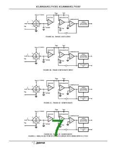
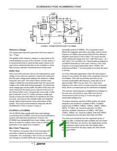
FIGURE 6. ADDING BUFFER GAIN TO ICL8068A
bandwidth product of 300MHz. The comparator output
follows the integrator ramp with a 3µs delay, and at a clock
frequency of 160kHz (6µs period) half of the first reference
integrate clock period is lost in delay. This means that the
meter reading will change from 0 to 1 with 50µV input, 1 to 2
with 150µV, 2 to 3 at 250µV, etc. This transition at midpoint is
considered desirable by most users. However, if the clock
frequency is increased appreciably above 160kHz, the
instrument will flash “1” on noise peaks even when the input
is shorted.
Reference Voltage
The analog input required to generate a full scale output is:
= 2V
V
.
REF
IN
The stability of the reference voltage is a major factor in the
overall absolute accuracy of the converter. For this reason, it
is recommended that an external high quality reference be
used where ambient temperature is not controlled or where
high-accuracy absolute measurements are being made.
Buffer Gain
At the end of the auto-zero interval, the instantaneous noise
voltage on the auto-zero capacitor is stored and subtracted
from the input voltage while adding to the reference voltage
during the next cycle. The result of this is that the noise
voltage is effectively somewhat greater than the input noise
voltage of the buffer itself during integration. By introducing
some voltage gain into the buffer, the effect of the auto-zero
noise (referred to the input) can be reduced to the level of
the inherent buffer noise. This generally occurs with a buffer
gain of between 3 and 10. Further increase in buffer gain
merely increases the total offset to be handled by the auto-
zero loop, and reduces the available buffer and integrator
swings, without improving the noise performance of the
system. The circuit recommended for doing this with the
ICL8068A/ICL71C03 is shown in Figure 6.
For many dedicated applications where the input signal is
always on one polarity, the dealy of the comparator need not
be limitation. Since the non-linearity and noise do not
increase substantially with frequency, clock rates of up to
approximately 1MHz may be used. For a fixed clock
frequency, the extra count or counts caused by comparator
delay will be a constant and can be subtracted out digitally.
The minimum clock frequency is established by leakage on
the auto-zero and reference caps. With most devices,
measurement cycles as long as 10 seconds give no
measurable leakage error.
To achieve maximum rejection of 60Hz pickup, the signal
integrate cycle should be a multiple of 60Hz. Oscillator
frequencies of 300kHz, 200kHz, 150kHz, 120kHz, 100kHz,
1
40kHz, 33 / kHz, etc, should be selected. For 50Hz
3
2
rejection, oscillator frequencies of 250kHz, 166 / kHz,
ICL8052A vs ICL8068A
3
125kHz, 100kHz, etc. would be suitable. Note that 100kHz
(2.5 readings/second) will reject both 50Hz and 60Hz.
The ICL8052A offers significantly lower input leakage
currents than the ICL8068A, and may be found preferable in
systems with high input impedances. However, the
ICL8068A has substantially lower noise voltage, and is the
device of choice for systems where noise is a limiting factor,
particularly in low signal level conditions.
The clock used should be free from significant phase or
frequency jitter. A simple two-gate oscillator and one based
on CMOS 7555 timer are shown in the Applications section.
The multiplexed output means that if the display takes
significant current from the logic supply, the clock should
have good PSRR.
Max Clock Frequency
The maximum conversion rate of most dual-slope A/D
converters is limited by frequency response of the
comparator. The comparator in this circuit is no exception,
even though it is entirely NPN with an open-loop, gain-
11

 ETC [ ETC ]