ST90158 - EIGHT-CHANNEL ANALOG TO DIGITAL CONVERTER (A/D)
9.8 EIGHT-CHANNEL ANALOG TO DIGITAL CONVERTER (A/D)
9.8.1 Introduction
supply noise rejection. In fact, the converted digital
value, is referred to the analog reference voltage
which determines the full scale converted value.
The 8-Channel Analog to Digital Converter (A/D)
comprises an input multiplex channel selector
feeding a successive approximation converter.
Conversion requires 138 INTCLK cycles (of which
84 are required for sampling), conversion time is
thus a function of the INTCLK frequency; for in-
stance, for a 20MHz clock rate, conversion of the
selected channel requires 6.9µs. This time in-
cludes the 4.2µs required by the built-in Sample
and Hold circuitry, which minimizes the need for
external components and allows quick sampling of
the signal to minimise warping and conversion er-
ror. Conversion resolution is 8 bits, with ±1 LSB
Naturally, Analog and Digital V MUST be com-
SS
mon. If analog supplies are not present, input ref-
erence voltages are referred to the digital ground
and supply.
Up to 8 multiplexed Analog Inputs are available,
depending on the specific device type. A group of
signals can be converted sequentially by simply
programming the starting address of the first ana-
log channel to be converted and with the AUTO-
SCAN feature.
Two Analog Watchdogs are provided, allowing
continuous hardware monitoring of two input chan-
nels. An Interrupt request is generated whenever
the converted value of either of these two analog
inputs is outside the upper or lower programmed
threshold values. The comparison result is stored
in a dedicated register.
maximum error in the input range between V
SS
and the analog V reference.
DD
The converter uses a fully differential analog input
configuration for the best noise immunity and pre-
cision performance. Two separate supply refer-
ences are provided to ensure the best possible
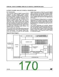
Figure 87. Block Diagram
n
INT. VECTOR POINTER
INT. CONTROL REGISTER
INTERRUPT UNIT
COMPARE RESULT REGISTER
7U
7L
6U
6L
THRESHOLD REGISTER
THRESHOLD REGISTER
THRESHOLD REGISTER
THRESHOLD REGISTER
COMPARE LOGIC
INTERNAL
TRIGGER
CONTROL
LOGIC
AIN 7
AIN 6
AIN 5
AIN 4
AIN 3
AIN 2
AIN 1
AIN 0
DATA REGISTER 7
DATA REGISTER 6
DATA REGISTER 5
DATA REGISTER 4
DATA REGISTER 3
DATA REGISTER 2
DATA REGISTER 1
DATA REGISTER 0
CONVERSION
EXTERNAL
TRIGGER
RESULT
ANALOG
MUX
SUCCESSIVE APPROXIMATION
A/D CONVERTER
AUTOSCAN LOGIC
CONTROL REG.
VA00223
170/199
9

 ETC [ ETC ]