ST90158 - STANDARD TIMER (STIM)
9.4 STANDARD TIMER (STIM)
Important Note: This chapter is a generic descrip-
tion of the STIM peripheral. Depending on the ST9
device, some or all of the interface signals de-
scribed may not be connected to external pins. For
the list of STIM pins present on the particular ST9
device, refer to the pinout description in the first
section of the data sheet.
– triggerable input mode,
– retriggerable input mode.
STOUT can be used to generate a Square Wave
or Pulse Width Modulated signal.
The Standard Timer is composed of a 16-bit down
counter with an 8-bit prescaler. The input clock to
the prescaler can be driven either by an internal
clock equal to INTCLK divided by 4, or by
CLOCK2 derived directly from the external oscilla-
tor, divided by device dependent prescaler value,
thus providing a stable time reference independ-
ent from the PLL programming or by an external
clock connected to the STIN pin.
9.4.1 Introduction
The Standard Timer includes a programmable 16-
bit down counter and an associated 8-bit prescaler
with Single and Continuous counting modes capa-
bility. The Standard Timer uses an input pin (STIN)
and an output (STOUT) pin. These pins, when
available, may be independent pins or connected
as Alternate Functions of an I/O port bit.
The Standard Timer End Of Count condition is
able to generate an interrupt which is connected to
one of the external interrupt channels.
STIN can be used in one of four programmable in-
put modes:
The End of Count condition is defined as the
Counter Underflow, whenever 00h is reached.
– event counter,
– gated external input mode,
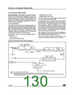
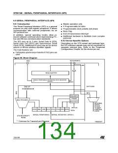
Figure 64. Standard Timer Block Diagram
n
INMD1 INMD2
INEN
INPUT
&
1
STIN
STH,STL
16-BIT
DOWNCOUNTER
STP
(See Note 2)
CLOCK CONTROL LOGIC
MUX
8-BIT PRESCALER
STANDARD TIMER
CLOCK
INTCLK/4
END OF
COUNT
CLOCK2/x
OUTMD2
OUTMD1
1
STOUT
OUTPUT CONTROL LOGIC
EXTERNAL
1
INTERRUPT
INTERRUPT
INTS
CONTROL LOGIC
INTERRUPT REQUEST
Note 1: Pin not present on all ST9 devices.
Note 2: Depending on device, the source of the INPUT & CLOCK CONTROL LOGIC block
may be permanently connected either to STIN or the RCCU signal CLOCK2/x. In devices without STIN and CLOCK2, the
INEN bit must be held at 0.
130/199
9

 ETC [ ETC ]