ST90158 - SERIAL PERIPHERAL INTERFACE (SPI)
9.5 SERIAL PERIPHERAL INTERFACE (SPI)
9.5.1 Introduction
■ Master operation only
■ 4 Programmable bit rates
■ Programmable clock polarity and phase
■ Busy Flag
The Serial Peripheral Interface (SPI) is a general
purpose on-chip shift register peripheral. It allows
communication with external peripherals via an
SPI protocol bus.
■ End of transmission interrupt
In addition, special operating modes allow re-
■ Additional hardware to facilitate more complex
2
duced software overhead when implementing I C-
protocols
bus and IM-bus communication standards.
9.5.2 Device-Specific Options
The SPI uses up to 3 pins: Serial Data In (SDI),
Serial Data Out (SDO) and Synchronous Serial
Clock (SCK). Additional I/O pins may act as device
selects or IM-bus address identifier signals.
Depending on the ST9 variant and package type,
the SPI interface signals may not be connected to
separate external pins. Refer to the Peripheral
Configuration Chapter for the device pin-out.
The main features are:
■ Full duplex synchronous transfer if 3 I/O pins are
used
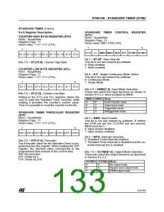
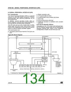
Figure 65. Block Diagram
SDI
SCK/INT2
SDO
READ BUFFER
SERIAL PERIPHERAL INTERFACE DATA REGISTER
( SPIDR )
R253
*
DATA BUS
END OF
TRANSMISSION
INT2
1
POLARITY
PHASE
0
MULTIPLEXER
BAUD RATE
INTERNAL
SERIAL
CLOCK
INTCLK
R254
TO MSPI
CONTROL
LOGIC
SPEN BMS
CPOL
SPR0
CPHA SPR1
ARB BUSY
SERIAL PERIPHERAL CONTROL REGISTER ( SPICR )
ST9 INTERRUPT
INTB0
* Common for Transmit and Receive
VR000347
n
134/199
9

 ETC [ ETC ]