ST90158 - STANDARD TIMER (STIM)
STANDARD TIMER (Cont’d)
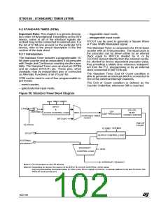
9.2.2 Functional Description
9.2.2.1 Timer/Counter control
bles the input mode selected by the INMD2 and
INMD1 bits. If the input is disabled (INEN="0"), the
values of INMD2 and INMD1 are not taken into ac-
count. In this case, this unit acts as a 16-bit timer
(plus prescaler) directly driven by INTCLK/4 and
transitions on the input pin have no effect.
Start-stop Count. The ST-SP bit (STC.7) is used
in order to start and stop counting. An instruction
which sets this bit will cause the Standard Timer to
start counting at the beginning of the next instruc-
tion. Resetting this bit will stop the counter.
Event Counter Mode (INMD1 = "0", INMD2 = "0")
The Standard Timer is driven by the signal applied
to the input pin (STIN) which acts as an external
clock. The unit works therefore as an event coun-
ter. The event is a high to low transition on STIN.
Spacing between trailing edges should be at least
the period of INTCLK multiplied by 8 (i.e. the max-
imum Standard Timer input frequency is 3 MHz
with INTCLK = 24MHz).
If the counter is stopped and restarted, counting
will resume from the value held at the stop condi-
tion, unless a new constant has been entered in
the Standard Timer registers during the stop peri-
od. In this case, the new constant will be loaded as
soon as counting is restarted.
A new constant can be written in STH, STL, STP
registers while the counter is running. The new
value of the STH and STL registers will be loaded
at the next End of Count condition, while the new
value of the STP register will be loaded immedi-
ately.
Gated Input Mode (INMD1 = "0", INMD2 = “1”)
The Timer uses the internal clock (INTCLK divided
by 4) and starts and stops the Timer according to
the state of STIN pin. When the status of the STIN
is High the Standard Timer count operation pro-
ceeds, and when Low, counting is stopped.
WARNING: Inordertopreventincorrectcounting of
theStandardTimer,theprescaler(STP)andcounter
(STL, STH) registers must be initialised before the
starting of the timer. If this is not done, counting will
start with the reset values (STH=FFh, STL=FFh,
STP=FFh).
TriggerableInputMode(INMD1=“1”,INMD2=“0”)
The Standard Timer is started by:
a) setting the Start-Stop bit, AND
b) a High to Low (low trigger) transition on STIN.
Single/Continuous Mode.
The S-C bit (STC.6) selects between the Single or
Continuous mode.
In order to stop the Standard Timer in this mode, it
is only necessary to reset the Start-Stop bit.
SINGLE MODE: at the End of Count, the Standard
Timer stops, reloads the constant and resets the
Start/Stop bit (the user programmer can inspect
the timer current status by reading this bit). Setting
the Start/Stop bit will restart the counter.
Retriggerable Input Mode (INMD1 = “1”, INMD2
= “1”)
In this mode, when the Standard Timer is running
(with internal clock), a High to Low transition on
STIN causes the counting to start from the last
constant loaded into the STL/STH and STP regis-
ters. When the Standard Timer is stopped (ST-SP
bit equal to zero), a High to Low transition on STIN
has no effect.
CONTINUOUS MODE: At the End of the Count, the
counter automatically reloads the constant and re-
starts.ItisonlystoppedbyresettingtheStart/Stopbit.
The S-C bit can be written either with the timer
stopped or running. It is possible to toggle the S-C
bit and start the Standard Timer with the same in-
struction.
9.2.2.3 Time Base Generator (ST9 devices
without Standard Timer Input STIN)
For devices where STIN is replaced by a connec-
tion to CLOCK2, the condition (INMD1 = “0”,
INMD2 = “0”) will allow the Standard Timer to gen-
erate a stable time base independent from the PLL
programming.
9.2.2.2 Standard Timer Input Modes (ST9
devices with Standard Timer Input STIN)
Bits INMD2, INMD1 and INEN are used to select
the input modes. The Input Enable (INEN) bit ena-
103/199
9

 ETC [ ETC ]