ST90158 - TIMER/WATCHDOG (WDT)
TIMER/WATCHDOG (Cont’d)
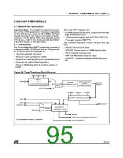
9.1.4 WDT Interrupts
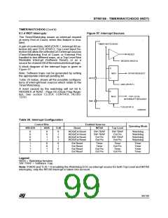
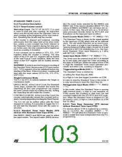
Figure 57. Interrupt Sources
The Timer/Watchdog issues an interrupt request
at every End of Count, when this feature is ena-
bled.
TIMER WATCHDOG
A pair of control bits, IA0S (EIVR.1, Interrupt A0 se-
lection bit) and TLIS (EIVR.2, Top Level Input Se-
lection bit) allow the selection of 2 interrupt sources
(Timer/Watchdog End of Count, or External Pin)
handled in two different ways, as a Top Level Non
Maskable Interrupt (Software Reset), or as a
source for channel A0 of the external interruptlogic.
RESET
WDGEN (WCR.6)
A block diagram of the interrupt logic is given in
Figure 57.
0
Note: Software traps can be generated by setting
the appropriate interrupt pending bit.
MUX
INTA0 REQUEST
INT0
1
Table 20 below, shows all the possible configura-
tions of interrupt/reset sources which relate to the
Timer/Watchdog.
IA0S (EIVR.1)
A reset caused by the watchdog will set bit 6,
WDGRES of R242 - Page 55 (Clock Flag Regis-
ter). See section CLOCK CONTROL REGIS-
TERS.
0
1
TOP LEVEL
INTERRUPT REQUEST
MUX
NMI
TLIS (EIVR.2)
VA00293
Table 20. Interrupt Configuration
Control Bits
Enabled Sources
INTA0
Operating Mode
WDGEN
IA0S
TLIS
Reset
Top Level
0
0
0
0
0
0
1
1
0
1
0
1
WDG/Ext Reset
WDG/Ext Reset
WDG/Ext Reset
WDG/Ext Reset
SW TRAP
SW TRAP
Ext Pin
SW TRAP
Ext Pin
SW TRAP
Ext Pin
Watchdog
Watchdog
Watchdog
Watchdog
Ext Pin
1
1
1
1
0
0
1
1
0
1
0
1
Ext Reset
Ext Reset
Ext Reset
Ext Reset
Timer
Timer
Ext Pin
Ext Pin
Timer
Ext Pin
Timer
Timer
Timer
Timer
Timer
Ext Pin
Legend:
WDG = Watchdog function
SW TRAP = Software Trap
Note: If IA0S and TLIS = 0 (enabling the Watchdog EOC as interrupt source for both Top Level and INTA0
interrupts), only the INTA0 interrupt is taken into account.
99/199
9

 ETC [ ETC ]